Let's Design and Build a (mostly) Digital Theremin!

Posted: 5/22/2023 9:20:05 PM
dewster

From: Northern NJ, USA

Joined: 2/17/2012

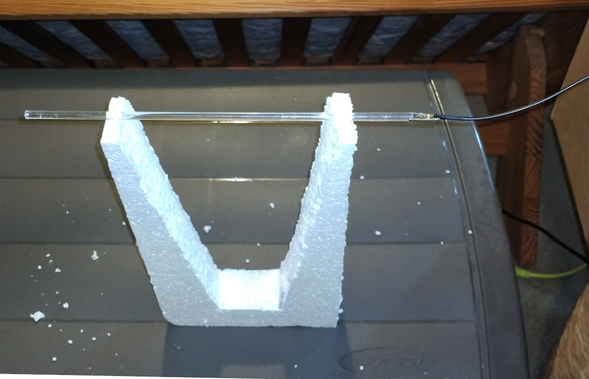
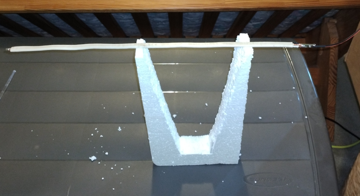
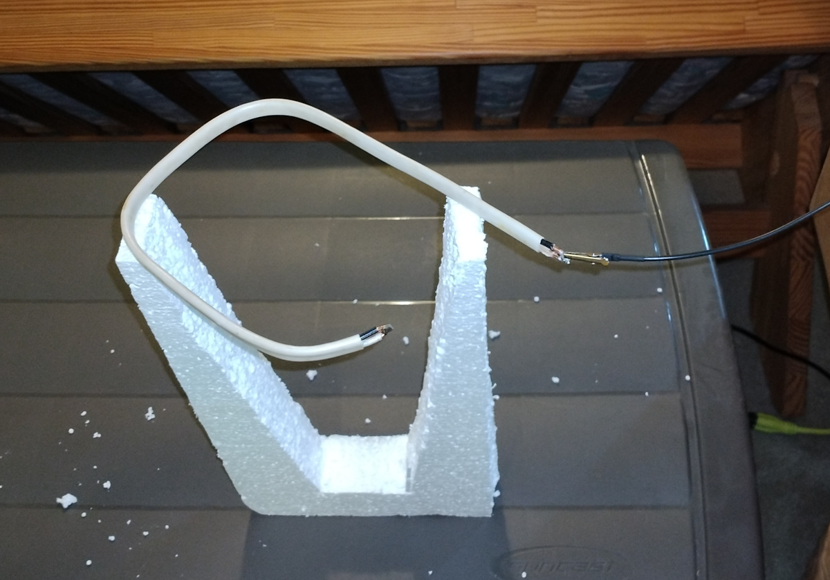
"4) Two small-diameter conductors (small diameter relative to their spacing) will each be less influenced by their neighbor than if larger diameter conductors are used.  Consequently the volume loop of picture 3 will electrically look more like a straight wire lying completely over plastic with very little loop effect caused by the folded back section influencing the other side.  Larger diameter conductors or a tighter loop should begin to show more of the capacitance-decreasing effect due adjacent common-mode E-fields that I was describing in our email."  - pitts8rh

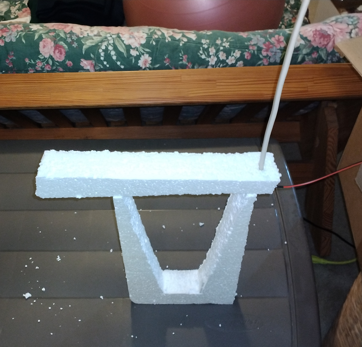
Thanks!  #1 thru #3 I get.  I was going more for qualitative than quantitative, but point taken.  Presumably I could hang the antennas from the ceiling with string and get more accurate results.  I was expecting the horizontal rod to have more intrinsic just due to more of it being closer to the ground, and that seems to be the case.  The curve having less intrinsic was a bit of a surprise, because I figured it would have more effective area than a rod, though perhaps closing the loop conductively would accomplish this?

But I'm not sure I completely understand #4?  There are three conductors in 12/2 wire and they're spaced pretty closely.  Would it help if I soldered them all together on both ends?  Or should I introduce even more in the way of intermediate shorts?  My intuition of electrical fields (largely sans the magnetic component) is that they are fairly mushy things, with a lot of blurring together at the detail level due to the general lack of directionality, but there could certainly be more nuance going on.

[ALSO] My rationale for why the above results are largely valid is the same as for why insulated antennas differ imperceptibly from uninsulated: the insulation comprises so little of the overall air dielectric that the effect is negligible.  Much longer antennas would behave more inductively, and then a nearby insulator could increase the self C, but these are so short compared to the wavelength that they're effectively just capacitive plates.  All of this to a first order, and as in all things physics one should trust but verify.  I'll give it a bit more meticulous shot tomorrow.

Posted: 5/23/2023 6:20:27 PM
dewster

From: Northern NJ, USA

Joined: 2/17/2012

Rod vs. Loop - Take 2

A re-run of yesterday's antenna experiments with a somewhat different setup.  Ideally one would hang the antennas from the ceiling with synthetic string of some sort, but the pendulum effect might take forever to calm down.  In lieu of that I opted for supporting the antennas on a block of Styrofoam, which the web tells me has a relative permittivity of 1.1.  The block was approx. 370mm tall x 200mm wide x 50mm thick, with a 320mm x 170mm  ‘V’ cut out of the upper portion to keep as much of it as reasonably possible away from the antennas.  This sitting on top of the same mostly empty large plastic storage bin.  The vertical configurations required an additional small strip of Styrofoam for support.

I soldered the three 12 gauge conductors together on the other end as well for these tests, so both ends were soldered.

The results were fairly similar, no earth shattering differences:


Above: Stray C calibration measurement using an acrylic rod to keep the alligator clip in position : 7.75pF


Above: Straight antenna horizontal C measurement : 5.25pF


Above: Curved antenna horizontal C measurement : 4.69pF


Above: Straight antenna vertical C measurement : 4.98pF


Above: Curved antenna vertical C measurement : 4.41pF

A valid criticism here would be that Styrofoam has a very low relative permittivity only because it is mostly air, and that there is more volume of it in this test setup compared to the plastic shoebox in the previous test.  But less of it is in close proximity with the horizontal antennas.

A real Theremin would have case and stand interactions, as well as interaction between the antennas, etc., so I'm just looking for a rough comparison between the horizontal loop and vertical rod in terms of ballpark numbers.

Posted: 5/24/2023 12:13:57 PM
dewster

From: Northern NJ, USA

Joined: 2/17/2012

Bad FPGA Board

Just got through checking and pumping 12 Waveshare CoreEP4CE6 boards that I bought back in February.  One wouldn't pump, not sure what's wrong with it but everything looks fine under magnification, the 3.3V, 2.5V, and 1.2V regulators are regulating, and it's not drawing excessive current.  Opened a ticket with Waveshare, will see what happens.

Noticed today that the price dropped to $65, wish I'd held off because I didn't need one until today - guess I'm still in hoarding panic mode.

https://www.waveshare.com/product/fpga-tools/core-boards-compact-boards/altera-core/coreep4ce6.htm

[EDIT] Waveshare did the right thing and sent me a replacement FPGA board, though I had to order another one (which I needed anyway) for that to happen.

Posted: 5/26/2023 1:58:10 PM
dewster

From: Northern NJ, USA

Joined: 2/17/2012

Digital Debounce Bi-Modal Weighting Rationale

Revisiting my decisions regarding the encoder digital debounce logic inside the FPGA.  Each contact is weakly pulled up via the programmable resistor at each FPGA pin, and when closed shorts this to ground, with no "datasheet recommended" analog debouncing.  Each contact input has a very high speed counter inside the FPGA that counts up or down depending on the state of the input, saturating at 0 and some maximum based on the debounce time.  The counter output then has separate high and low trigger points connected to the output state register to impart hysteresis, so noise won't cause rapid output changes at a common trigger point.

At one point I decided to weight the low state 3x more heavily than the high state, and looking at it again after some time had passed I couldn't remember why - it seemed rather alarmingly like a mistake.  But after some thought it makes sense, and I wanted to note it here.

When a contact is open, unless there is something external pulling it around (which could potentially happen in a Theremin due to the strong C fields and weak pullup) by definition there will be no contact bounce.  When a contact is closed there can be a lot of bouncing going on, particularly with noisy encoders like Bourns (grrr) or worn out encoders.  So the prudent thing to do when the input is low then is to make the counter go more quickly to 0, but when high have the counter float up more slowly so as not to be fooled by bouncing.

In a nutshell: In the absence of other types of noise, we can trust a low to be real, but a high could be real or just contact bounce, and if it is contact bounce then a longer debounce time will help to pave over it.  Speedier time to low will also improve response time to something like a pushbutton.

In retrospect, I should have done all of this in software with a 48kHz interrupt, which is speedy enough and much more flexible than FPGA logic.  The vast majority of the time the user will only be twisting a single encoder at a time, so connections and processing can be considerably simplified.

Posted: 5/31/2023 5:09:16 PM
Buggins

From: Porto, Portugal

Joined: 3/16/2017

Encoder pin + connection trace has some capacitance, and has fast discharge and slow charge. So I think you should expect non-symmetric nature of bouncing noise.

Can you sample encoder signals from real hardware with sample rate you are using, collect them for some time interval, and then transfer to PC?
I believe seeing recorded bounce signal may help to choose proper filter for FPGA side de-bouncing.

Posted: 6/2/2023 12:27:09 AM
ekahn

Joined: 11/2/2022

The Bourns datasheets specify the following debounce circuit for the encoder leads:

Posted: 6/2/2023 1:44:15 PM
dewster

From: Northern NJ, USA

Joined: 2/17/2012

"Encoder pin + connection trace has some capacitance, and has fast discharge and slow charge. So I think you should expect non-symmetric nature of bouncing noise."  - Buggins

Agree.

"Can you sample encoder signals from real hardware with sample rate you are using, collect them for some time interval, and then transfer to PC?
I believe seeing recorded bounce signal may help to choose proper filter for FPGA side de-bouncing."

If things like the FPGA weak pull-up and the bouncing were more constant that would be the way to go (http://www.thereminworld.com/forums/T/28554?post=221660#221660).  Small knobs tend to encourage fast twisting, like 200Hz at the contacts, so the debounce time constant should be somewhat shorter than 5ms.

"The Bourns datasheets specify the following debounce circuit for the encoder leads" - ekahn

To really do it right they should suggest a different encoder! ;-)  That circuit makes a lot of sense because the high RC time constant is 2x that of low (discussed here: http://www.thereminworld.com/forums/T/28554?post=222056#222056).  But the time constant at 0.2ms is a little short IMO.

This is what's going on with the FPGA logic and Hive SW: http://www.thereminworld.com/forums/T/28554?post=219949#219949

Posted: 6/3/2023 1:10:28 PM
Mr_Dham

From: Occitanie

Joined: 3/4/2012

I have the feeling that bourns encoders are much less bouncy after 2 years.

Is it that the track became smoother with this initial wear?
Or is it just me and my habituation to their characteristics?

Posted: 6/4/2023 12:07:42 PM
dewster

From: Northern NJ, USA

Joined: 2/17/2012

"I have the feeling that bourns encoders are much less bouncy after 2 years.  Is it that the track became smoother with this initial wear?  Or is it just me and my habituation to their characteristics?" - Mr_Dham

That's interesting to hear!  I suppose wear could make the encoders less problematic, though the opposite has been my experience. 

To check them (the LEVELS page works best for this) test the following in both directions:
1. Turn slowly at least a full revolution: Each detent should cleanly register.
2. Spin quickly a few times: The velocity should give roughly equal big jumps in both directions.
3. Spin quickly up against max / min on the screen: The max / min value shouldn't flicker or change.

I just changed the flaky encoders in Rob Schwimmer's P3 because they were rather spectacularly failing test #1.  Some slow clicks wouldn't register, but then just lightly touching the knob would cause a change - potentially big trouble if it's your voice selector!  These were inexpensive generic units Roger purchased (off eBay?) with the same encoder direction as the Bourns (SYSTEM:Erev[0]). 

The inexpensive generic replacement units have been working like champs.  They are from eBay but have reverse sense (SYSTEM:Erev[1]) and I'm wondering if there is a pattern here?  Also, the Bourns are low profile, Roger's and my units are regular profile.

Roger told me he disassembled a flaky unit and found the detent mechanism not tightly coupled to the switching mechanism, which explains the failure.

Anyway, I can see how encoders in general have a bad reputation, and I'll gladly replace any that are acting up in the kits.

Also, I wonder if an application of DeoxIT D100L-25C might help the ones that just have contact noise: https://www.amazon.com/dp/B0000YH6F8

Posted: 6/4/2023 1:09:51 PM
Mr_Dham

From: Occitanie

Joined: 3/4/2012


Well... The test results don't seem too bad.

Only Test 3 gives a slightly noisy result on two encoders during the first few revolutions, then after spinning them once or twice, they remain stable at maximum/minimum.


I've always wondered about contact cleaners. They can solve potentiometer noise problems temporarily, but don't they move the problem elsewhere? I don't know...

You must be logged in to post a reply. Please log in or register for a new account.