Let's Design and Build a (mostly) Digital Theremin!

Posted: 11/21/2016 6:01:42 PM
dewster

From: Northern NJ, USA

Joined: 2/17/2012

Found a nasty flaw in the way I was parsing labels.  Explicitly assigned labels work fine, but those that are implicitly assigned can be broken because addresses can require one, two, or three opcode slots when assigned to a literal, which can move all of the code forward zero, one, or two opcode slots per literal depending on the address value.  But the label address value can be dependent on the location of the label, so it's a chicken / egg thing.  For instance, say we want to place a label value on stack 0, but the label is implicitly assigned somewhere higher in address space.  We can't do the assignment unless we know the address, and we can't know the address unless we do the assignment!

One can work this sort of problem out on paper, so a solution exists.  But formally coding it is another thing, particularly with a fixed number of passes over the code.  One could probably gather all the info and do some sorting and thresholding, but it may be easiest to do repeated passes over the code, updating the label table, and exiting when the table stops changing.  This will be the first approach I try.  If labels weren't so useful I'd just drop it altogether, but I'm finding coding with them really speeds things up and removes a lot of pain and bookkeeping.

===========

Am also polishing the command line interface, when it's done it should be easily extensible to do other things.  Engineers get criticized for spending inordinate amounts of time automating and optimizing things (XKCD), time one may not make up by making those things run more smoothly.  But this fails to take into account all of the necessary experimentation and self-training going on - which enables future projects to be developed that much faster.  If we could live forever an engineer might be your go-to person for getting lots of stuff done quickly because they will have worked long and hard on lots of problems, with ready solutions to many thorny issues.  As for premature optimization, well it's often difficult to tell where you are in a project, so it can be difficult to tell if your efforts are indeed premature.  Experts will tell you to make a quick prototype, then toss it and make another, etc. but often the project isn't a good fit for that advice.  E.g. my Hive simulator code is about as rats-nesty as I can tolerate / follow, and I often need to add features to it which isn't all that easy, but I'm not about to scrap it and start over.  

===========

Once the above is behind me I will attempt an experiment in order to characterize the noise at the pitch antenna.  In the DPLL, the operating point numbers are fed to a 4th order low-pass digital filter at double the edge rate (~5MHz).  This filter lops off noise starting at ~1kHz and pretty much kills everything above 1/2 the sampling rate (48kHz).  So I should be able to send the output of this filter more or less directly to the SPDIF TX logic and record it as audio in Audition.  From there I will be able to see what is going on both spectrally and in terms of overall amplitude.  This will allow me to assess countermeasures implemented in order to reduce the noise in SW or in FPGA hardware (comb filter, variable LPF, etc.).

The numbers from the DPLL are likely good enough to use as-is, but it never hurts to have more precision than you need, particularly when a fair amount of math will be performed on them.

Posted: 11/23/2016 6:10:40 PM
dewster

From: Northern NJ, USA

Joined: 2/17/2012

Was literally burning the midnight oil coding last night, slogging through the nested IFs, trying to catch and handle all of the label scenarios I could imagine - it's remarkably nuanced.  Got it working and hit the hay, then got up this morning to work out the final bugs and apply some shoeshine.  In the process I was able to finally reconcile the minus sign '-' as a valid HAL symbol in the parser, dealing with negative numbers and various fancy assembly code constructs systematically in the pre-processor.  The final pass is now more of a post-processor, where some absolute jumps get turned into relative jumps.

So HAL parsing goes like this (all generated code files are tokenized):

1. Split the source HAL file into tokenized code (hal_code.tmp) and end of line comment (hal_eol.tmp) files.

2. Read the code file and pre-process it to hal_pre.tmp.  Here we deal with negative numbers, as well as opcode convenience constructs not directly supported by the processor.  This makes downstream parsing easier too.

3. Read hal_pre.tmp, put explicit label values in the table and delete the assignment statement, and write the results to hal_lbl0.tmp.

4. Read hal_lbl0.tmp, replace all explicit labels with table values, and write the results to hal_lbl1.tmp.

5. Read hal_lbl1.tmp and place the remaining implicitly assigned label values (addresses) in the table.  Refer to the table for all label values as the file is parsed repeatedly as many times as it takes until the table values are stable.  Delete beginning of line labels, replace all remaining labels with table values, and write the results to hal_lbl2.tmp.

6. Read hal_lbl2.tmp, convert certain jump constructs from absolute to relative addressing, and write the results to hal_post.tmp.

7. Parse hal_post.tmp and hal_eol.tmp files to the memory array and delete all temporary files.

It might seem that steps 3 and 4 could be combined, but doing so would make it harder to detect table collisions and null assignments.  As with all other parsing I've implemented, original line numbers are retained throughout, and parsing halts on the first error encountered (reporting the line number).  This makes it a lot easier to figure out what when wrong where when it inevitably does.  The stand-alone compiler has a command line switch option that retains the temp files for debugging purposes.

 
Here's a small example of HAL processing.  This is the HAL source code for writing a byte to memory (memory is addressed in 16 or 32 bit "chunks" hence the need for this subroutine and a similar one for reading bytes from memory):
 
lbl[0x14] s2 >>= 1 // * SUB: WR BYTE * (0:data, 1:addr, 2:idx, 7:rtn | -)
P1 += P2// base addr + idx/2
s3 :u= mem[s1]// read mem
P0 <<= 24// in_byte to MSB position
P2 >>r= 1// test idx odd
(P2<0) ? pc := lbl[0x15]// idx odd=wr_hi
P3 >>= 8// wr_lo: hi_byte to MSB position
pc := lbl[0x16]// do common
lbl[0x15] P3 <<= 24 // wr_hi: lo_byte to MSB position
P0 >>= 24// in_byte to LSB position
lbl[0x16] P3 |= P0 // common: combine
P3 <<r= 8// rotate to final position
mem[P1] := P3// write mem
pc := P7// * sub end * return
 
 
Here is the code after being tokenized:
 
lbl [ 0x14 ] s2 > > = 1 
P1 + = P2 
s3 : u = mem [ s1 ] 
P0 < < = 24 
P2 > > r = 1 
( P2 < 0 ) ? pc : = lbl [ 0x15 ] 
P3 > > = 8 
pc : = lbl [ 0x16 ] 
lbl [ 0x15 ] P3 < < = 24 
P0 > > = 24 
lbl [ 0x16 ] P3 | = P0 
P3 < < r = 8 
mem [ P1 ] : = P3 
pc : = P7 
 
 
And here is the code after being post-processed:
 
s2 < < = -1 
P1 + = P2 
s3 : u = mem [ s1 + 0 ] 
P0 < < = 24 
P2 < < r = -1 
( P2 < 0 ) ? pc + = 2 
P3 < < = -8 
pc + = 2 
P3 < < = 24 
P0 < < = -24 
P3 | = P0 
P3 < < r = 8 
mem [ P1 + 0 ] : = P3 
pc : = P7 
 

All of the labels here are implicitly assigned, so the beginning of line labels are removed, and the remaining are turned into relative jump distances.  The convenience expression "mem[s1]" is converted to the standard expression with zero offset "mem[s0+0]".   All immediate right shifts and rotates are converted into left shifts and rotates, with the immediate shift value negated.  Other expressions not shown here like ++ increments and -- decrements get turned into += 1 and += -1 respectively.

This work is pretty tedious in C++, other languages likely implement parsing in a more natural way.  Now, back to the CLI coding in HAL.

Posted: 12/1/2016 6:22:16 PM
dewster

From: Northern NJ, USA

Joined: 2/17/2012

Still pondering the command line code structure.  Found this today via hacker news: https://interpreterbook.com/ which is kind of interesting as he probably addresses many of the issues I've encountered while implementing the HAL assembly language, as well as the Hive command line interpreter.  The command line is actually more difficult because it has to be done in limited hardware / software, which prevents me from using things like multiple intermediate buffers.

At the moment I'm leaning towards buffering the command line like everyone else seems to do, and that is via a circular buffer, with read/tail and write/head modulo pointers.  My previous command line code buffers everything directly as tokens, but that prevents the use of destructive backspace editing (mainly because "undoing" input values building base 10 tokens is problematic) - the lack of which I've found to be pretty frustrating to use.  The RX UART is only double buffered, so one either runs the RX interrupt to the software process, or oversamples the RX register somehow.  I think I'll go with using the 48kHz audio sample interrupt to do this as it is ~5x the ~10kHz byte rate (the audio int is quite handy). The interrupt process will look at the incoming byte, and if it is not BKSP (backspace) stick it in the current slot and increment the write pointer.   If it is BKSP it will decrement the write pointer if it is not equal to the read pointer.  I could include ESC (escape) here and have it set the write pointer equal to the read pointer, but that seems a little scary.

The read process then doesn't have to deal with BKSP at all (which would be a royal pain), but it still must figure out when to process tokens.  I keep forgetting that the command line is interactive, and that the serial stream feeding the command line, whether an actual human banging on the keyboard, or automated via TeraTerm, will wait and look for a new line as confirmation that the processor has consumed & processed the current command before issuing another.  So the read side can leisurely look for a change in characters (head PTR - tail PTR, modulo) with a command character at the end (white space, function key, etc.).

I want to make it possible to respond to things like single function keys being pressed without hitting the enter key (or adding some other white space to the end).  I also want to make all of the sub processes as generic as possible so I don't have to reinvent the wheel every time I make a fundamental change to the way the command line functions.  It's taken me a fair amount of thought to get here (where everyone else ends up, LOL) so I'm not all that keen on revisiting it yet again.  

Posted: 12/7/2016 4:16:44 AM
3.14

From: Buenos Aires, Argentina

Joined: 9/14/2008

Hi.

Wow this is a great thread!!

I love theremins but only constructed an EW (from scratch). I didn't like the EW very much (the sound and the thermal drift, the manual calibration, etc). 


I like the idea of having a minimal analog front end which receives the fixed pitch frequency from the digital part, and then does the heterodyning in the FPGA.  Also I would implement a similar idea for the volume antenna. And for sure some beautiful synthesis of the ideal theremin sound...


I´m sure that from the study of this thread (I´m at page 4 :)) I will find the inspiration I need.

But first just a little question, as I´m a newbie in FPGAs... and Intl shipping is slow here... so I'd like to order now some FPGA to start with when I'm ready. I don't care if I have to rewrite all the code of program myself the thing, as learning FPGA is part of the fun... I was looking for example at the Altera Cyclone II EP2C5T144 which is quite inexpensive (something like USD 15). Would it be enough?

Thank you!


Posted: 12/7/2016 4:56:31 AM
dewster

From: Northern NJ, USA

Joined: 2/17/2012

"I was looking for example at the Altera Cyclone II EP2C5T144 which is quite inexpensive (something like USD 15). Would it be enough?"  - 3.14

Cyclone 2 is kind of old, I'd suggest Cyclone 3, or better yet 4.  Can you purchase things from China or Korea via eBay?  If so I'd recommend this EP4CE10F17C8N board from Waveshare:

http://www.ebay.com/itm/EP4CE10F17C8N-EP4CE10-FPGA-ALTERA-Cyclone-IV-Evaluation-Development-Core-Board-/131816136496?hash=item1eb0da9f30:g:fQAAAOSwt7pXOUO0

You'll need a USB Blaster to pump it up.  FPGA's aren't for the faint-hearted, it's taken me forever to get comfortable with them and really understand digital design, but they are really open-ended.

This thread isn't so much about traditional heterodyning Theremins, but more linearized digital LC capacitive sensors as the next level of Theremin technology.  Lately it's (perhaps unfortunately, particularly for readers) been more about my vanity soft processor (Hive) which forms the core of this project.

Posted: 12/7/2016 9:16:02 PM
3.14

From: Buenos Aires, Argentina

Joined: 9/14/2008

That's great. Thanks for the advice! 

Which version of the variable oscillator would you recommend? Else, I would start the experiment with the variable pitch oscillator from etherwave, as I already have it working (that one around Q1&Q2 http://www.theremin.info/index.php?module=-&type=file&func=get&tid=15&fid=image&pid=54)

Also (I think it has been discussed, but not sure about the conclusions), the linearity of the antenna, is that important? I mean, cannot it be corrected in FPGA-Ware? (how should one call it? Firmware?) 

I've seen that you experimented with SPDIF output which is cool. I was thinking in sending digital audio to a USB DAC (M-Audio Fast Track) which I have lying around, problably SPDIF is even a better idea.

Cheers!

Posted: 12/7/2016 9:52:43 PM
dewster

From: Northern NJ, USA

Joined: 2/17/2012

"Which version of the variable oscillator would you recommend? Else, I would start the experiment with the variable pitch oscillator from etherwave, as I already have it working..."  - 3.14

I would NOT recommend the EW oscillator or any oscillator based around differential pair transistors.  The topology works OK if there is an EQ coil in series with the antenna, but will give you a fairly distorted sine wave otherwise.  And differential pairs are kind of slow, and so tend to produce feedback phase error.  I don't recommend any oscillator that stimulates the tank via the collector (or FET drain) as this connection will reverse bias on large negative swings of the LC tank.  I also don't like oscillators that have DC flowing through the tank inductor.  Just because Bob Moog, or Theremin himself, used an oscillator is not a good enough reason for anyone else to do so without fully understanding why, as well as the alternatives.

Without getting into it too deeply, one of the main things you want in an oscillator is high Q.  High Q can give large voltage swing for little energy input, thus swamping environmental noise and keeping heat to a minimum (to keep thermal drift low).  I say CAN because the phase of the feedback is also crucial, if it is off by just a little bit you won't get maximum voltage swing.  If you are building a digital capacitance sensor Theremin rather than a heterodyning Theremin, then you want an oscillator with the highest sensitivity to changing capacitance, and this means you can't pad the antenna or tank or tank sense with a lot of capacitance (ideally none).  For the above reasons I chose to digitally stimulate the tank, and sensing is also digital.  You also want to use a plate antenna here instead of a rod.

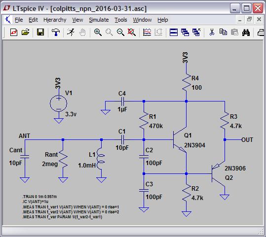
If you really want an external, transistor driven oscillator, you might try my Colpitts NPN (note that Cant and Rant are NOT components, they are parasitics of the antenna - and you really, really want to regulate the 3.3V supply):

"Also (I think it has been discussed, but not sure about the conclusions), the linearity of the antenna, is that important? I mean, cannot it be corrected in FPGA-Ware? (how should one call it? Firmware?)"

If you're building a digital capacitance sensor Theremin you can mathematically work backwards in software via the LC resonance equation to get capacitance.  The capacitance is highly linear to the inverse of hand distance, so no linearization beyond this is likely necessary (I'm nearly at this point myself).  If you are building a heterodyning Theremin then all you can do is employ an EQ coil to improve linearity.  Tuning this setup is difficult (two LC resonances and one local frequency), and you're stuck with the note distances that it gives you.  FredM was experimenting with an electrically tunable EQ inductor, but that's a lot of trouble to go to for a fairly inflexible setup.  It's better IMO to decouple the C sensing from the sound generation.

"I've seen that you experimented with SPDIF output which is cool. I was thinking in sending digital audio to a USB DAC (M-Audio Fast Track) which I have lying around, problably SPDIF is even a better idea."

SPDIF gives you electrical isolation via optical cabling, which is quite nice.  The audio noise floor really benefits from this, and it's one less wire hanging off the Theremin causing trouble.

Posted: 12/8/2016 3:50:37 AM
3.14

From: Buenos Aires, Argentina

Joined: 9/14/2008

Oh ok I think the digital capacitance sensor, decopled, to a synth which outputs through SPDIF is quite cool.

So you're using the AFE described in the first pages? The 4011 based one? 

Posted: 12/8/2016 3:53:30 AM
dewster

From: Northern NJ, USA

Joined: 2/17/2012

"So you're using the AFE described in the first pages? The 4011 based one?"  - 3.14

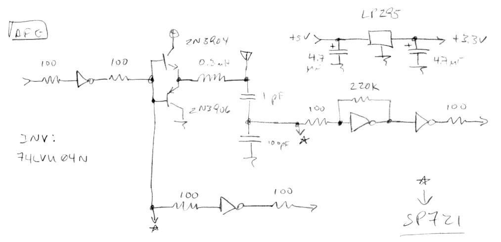
No, the one based on the 74LVU04N on page 112 (the 4011 works but is kinda slow):

I have two copies of this up and running, one for each hand (pitch and volume).  The volume side uses a 2mH inductor.  And the above schematic isn't 100% correct, I have two inverters in series on the bottom rather than one (to make all the digital latencies the same), making a total of 5 in use of the 6 in the package.  FPGA drive is a dithered NCO, feedback is a simple XOR gate coupled to an up/down counter (with some digital limiting).

I should probably put an index in the first post to help bring newcomers such as yourself up to speed on where things are now.  Four and a half years of posting (yikes!) can be a lot to wade through.  Many of my first instincts were pretty good, but I know tons more about this stuff then when I started out.  Theremin research can be a mine field (lots of well-worn dead-ends), but it can also be quite edifying if you approach it with an open mind.

Posted: 12/8/2016 12:33:53 PM
3.14

From: Buenos Aires, Argentina

Joined: 9/14/2008

Yeah, you could as well setup a github repository with code/circuits/excels and just put last versions there.

I can help with that if you wish.

So both coils 0.3 and 2mH are calculated with the excel in your mediafire repo?

Here it is very common to have .18mm wire, I think it's like AWG33.

Also I wonder if for the volume part there is a NCO adjusted by PLL to get 90 deg phase or you just measure phase shift. I guess I should dig into the code to answer myself...


You must be logged in to post a reply. Please log in or register for a new account.