Let's Design and Build a (mostly) Digital Theremin!

Posted: 10/14/2018 6:34:53 PM
dewster

From: Northern NJ, USA

Joined: 2/17/2012

The Hardwareing: Fashion Shots

Some more pix of the outsides and insides.  The boxes are mounted on sleazy CCTV camera mounts (use something else! like the most excellent though somewhat pricey RAM ball mounts I have in the parts list) that barely keep things in position without torquing down on the cheesy plastic thumbscrews so hard it feels like they're going to snap off.  The wooden stick base is a 3/4" thick x 3" wide x 900mm long piece of scrap plywood I scrounged from the garage. The control box and the microphone mount underneath are located in the center of the 900mm length, the antenna mounts at either end.  I've got the volume antenna box mount on the bottom of the plywood, you could probably mount it on the top instead if whatever you're using for mounts articulates sufficiently.


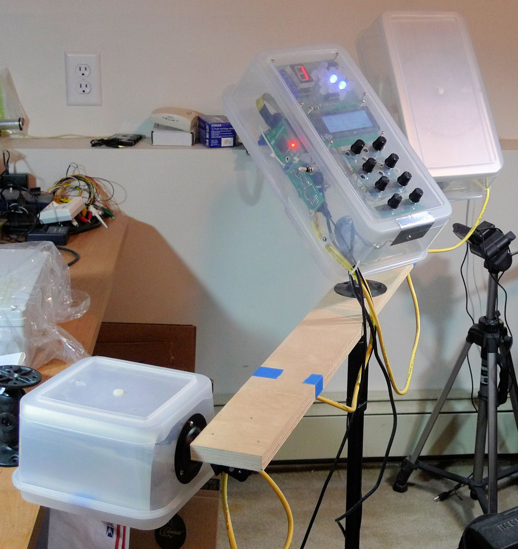
Make love to the camera baby!  (Please pardon my messy lab and work area, I'm a bit of a pig.)


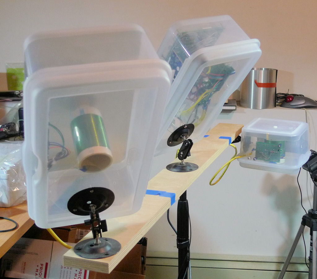
A better view of the mounts (and the sty).


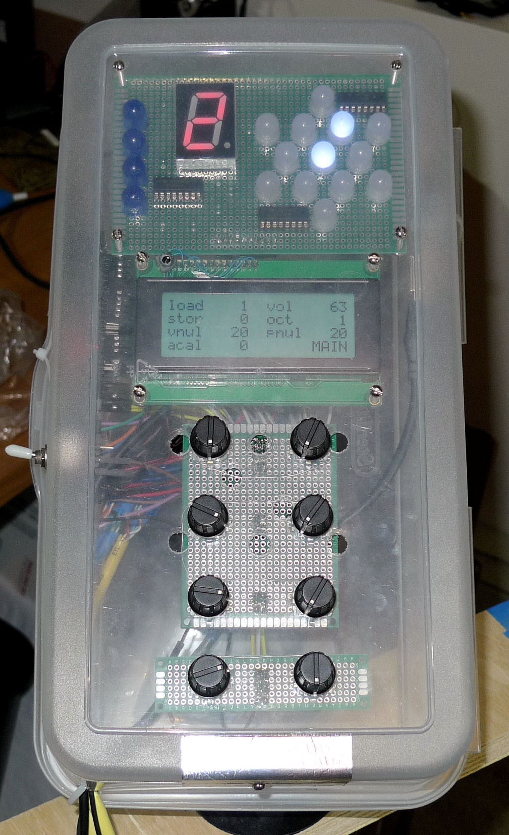
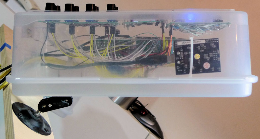
The control panel.  LED tuner a the top, LCD display at the center, rotary encoders below that, ESD pad along the bottom edge.


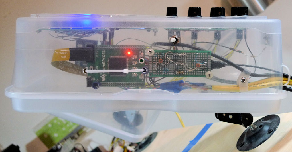
The left side.  That's the FPGA board to the left, the SPI EEPROM / TOSLINK TX / power distribution board to the right, and a small toggle switch above it for power.  Note that the Altera USB-Blaster ribbon is unfortunately rather captive here.


The right side.  That's my Altera USB Blaster to the right, sans it's plastic enclosure give the zip tie something to grip, but mainly to give access to the programming ribbon cable so as to avoid power cycle catastrophes.  If you aren't doing a lot of FPGA development then you probably don't need to co-locate the programmer with the FPGA board, but do somehow provide easy access to the programmer pins on the FPGA board, perhaps via a header extension or ribbon cable or similar.  You might want to buy a second USB extension cable for the programmer if you end up using it a lot.


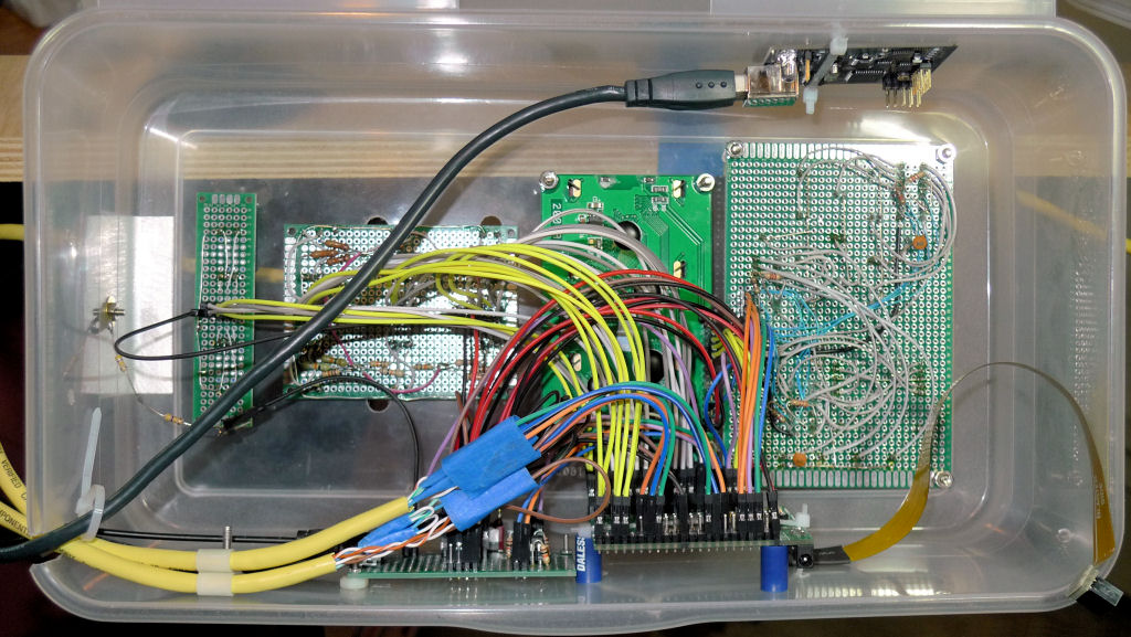
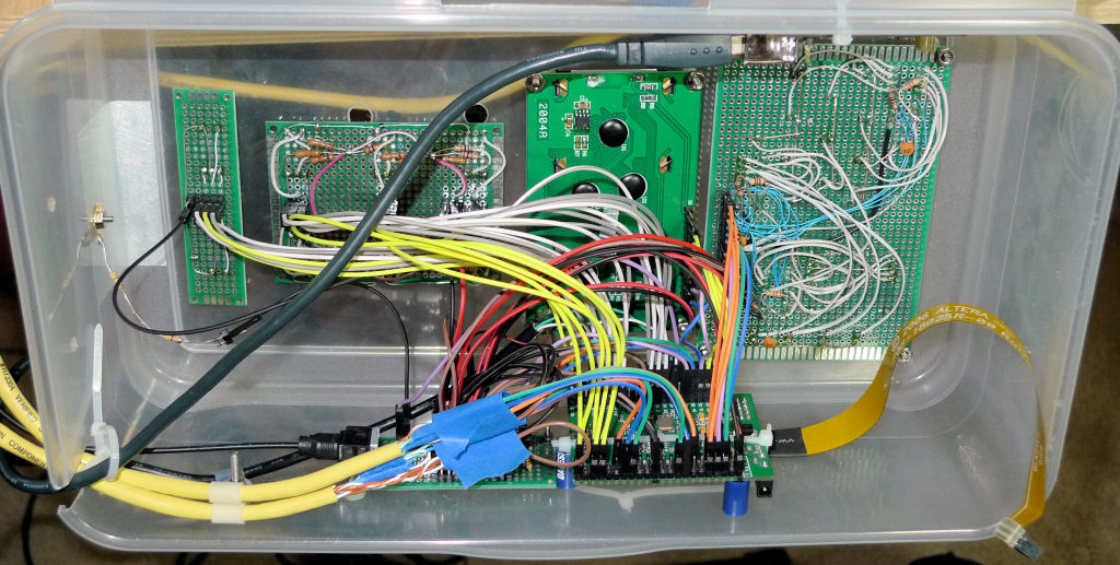
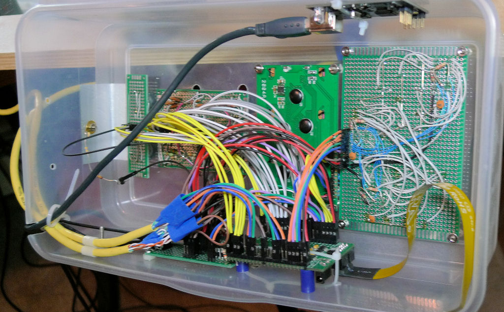
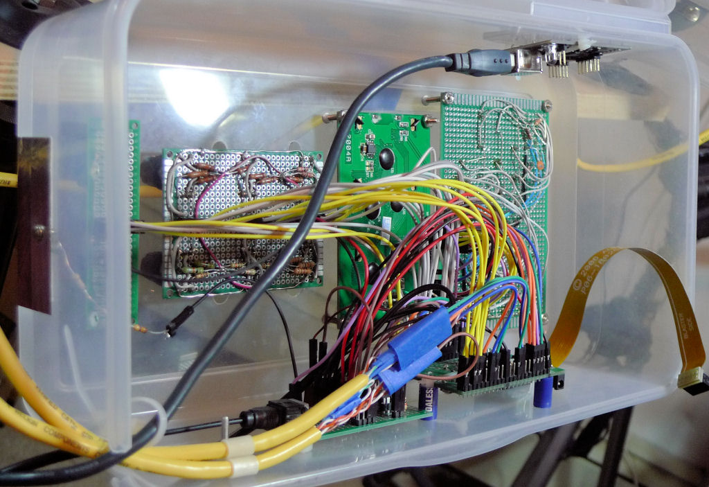
Some different angled views of the inside of the control box.  Spacers are nylon nuts or ballpoint pen case cut down.  Stuff held in place with screws & nuts / zip ties.  If you look closely you'll see that the 2 x 3 encoder board has discrete pullup resistors (10k IIRC) and the 2 x 1 doesn't.  There are programmable pullups inside the FPGA so no external resistors are necessary, and there just isn't any reason to remove them at this point.

You can also see the back of the LCD panel here, the small IC and passives just to the right of "2004A" comprise the 3.3V => 5V level shifter.  If they're not there then EastRising sold you the wrong (3.3V logic / 5V LCD) part.

Posted: 10/14/2018 6:38:26 PM
pitts8rh

From: Minnesota USA

Joined: 11/27/2015

I just bought the cheapest fastest Amazon Prime connectors:

https://smile.amazon.com/gp/product/B00E1LBWUQ/ref=oh_aui_detailpage_o00_s00?ie=UTF8&psc=1


If you keep the plastic boxes you could call it the EtherWare.  Otherwise the Wallin Therepetic (that's a Barney Fife thing).  Or go highbrow with anything in Latin:

Vox Aetheris,
Vox Aere,
Musica Caeli,
Musica Sine Tactu,
Musica Machina,
Motus Musica, or the ultimate
Dewster's Musicis Cibus Buxum Repono

Or just the simple Wallodia

Have fun.

Posted: 10/14/2018 10:37:24 PM
dewster

From: Northern NJ, USA

Joined: 2/17/2012

Thanks!  Wallodia!  (I hate my last name..)  Vox Aetheris is really hoity-toity sounding, I like it. 

I think the best names are those where you aren't sure if you're pronouncing them correctly (like Moog: moooog or mogue?).  One of the FPGA FAE's that visited me now and then started up the B3 synthesis firm Voce (and lived to tell about it) though IIRC the economics drove him out, a shame.  Musical notation uses Italian among other things, so "Voce Aeria" for air voice?  The Google Translate pronunciation runs it together to sound like one word, so it's probably confusing enough for us monolingual US'ns. I might be typing and saying (and if I'm extra lucky reading and hearing) this for the rest of my freakin life, so gotta be extra careful.

Putzing around this afternoon: [MP3].  The violin needs some adjustment.  Always on the lookout for lately for slow, sad songs that adapt well to violin / viola / cello.

[EDIT] Played it some more ("Motherless Child" negro spiritual on cello) and like the timing & phrasing of this better: [MP3] (I gotta stop posting stuff after only playing it a couple of times).

Posted: 10/15/2018 3:10:36 PM
pitts8rh

From: Minnesota USA

Joined: 11/27/2015

What are your oscillator frequencies?  I apologize if it's been mentioned multiple times elsewhere, but I'll admit that I haven't read everything yet.  I was scanning around post 1605, but I didn't see it, and it might be worth adding the frequencies there just for completeness.

The reason I ask is because I want to try something that I said I wasn't going to do, and that is deviate from your design a bit.  For purely mechanical design reasons I would like to use a 1.5" PVC core for the volume antenna (same core as the pitch, although I can still use finer wire).  To get to 4mH I could use even finer wire than AWG34 and/or probably introduce a segment of 10mm diameter ferrite.  While testing the pitch coil made per your first option with 260 turns, I was able insert this small ferrite to get up to 4.8mH with the SRF still in the MHz range. 

If necessary I can easily make the 2" coil and adapt it physically, but I'd like to start with the 1.5" if possible. 

BTW, thanks for all of the previous pictures.  I'm starting to understand how it all goes together, and I have enough to go on for now, except for the periodic questions as I actually put things together.

Posted: 10/15/2018 6:17:37 PM
dewster

From: Northern NJ, USA

Joined: 2/17/2012

"What are your oscillator frequencies?"  - pitts8rh

Good question.  I just stuck my frequency counter with a short antenna on it about 6" away from each plate:

963 kHz : PITCH
742 kHz : VOLUME

Of course, the intrinsic C of the plate (and its more or less immediate surroundings) will play into this too.  The larger the plate area the higher the C and the lower the frequency.  So one way to ease the volume coil construction would be to make the volume plate area larger.

I have very limited experience with ferrite as a core here.  There will be some temperature drift, and magnetization losses that will lower the phase gain and the tank Q, but whether those will be significant enough to matter I can't say.  The DPLLs in the FPGA SV code are fully parameterized, so you can just change the operating frequency and Q and recompile if necessary.  They should operate over a pretty wide range as-is, though perhaps not entirely optimally (the usual suspects: resolution, loop gain, loop bandwidth, stability, etc.).  I wouldn't go too high in frequency as the dither is necessarily sized to one generate / sample clock period, which in this case is a bit less than 400MHz.  So the pitch side dither is around 1MHz/400MHz, or about 52dB down. And dither is one hard limit on SNR.

I might try 36AWG, but any finer gets pretty tedious hand directing the feed on the jig.  I'm pretty sure even AWG40 would work fine (if you can manage it).

Have you tried my Excel coil calculator?  It underestimates L a bit compared to the final deal, I think mainly due to the windings not being as close due to the physical dimensions of the wire and any slight bends and such being inexact.  Any winding spreading lowers L.

ALSO: something I meant to tell you before, the pinout on the FPGA is entirely malleable.  There are 4 LEDs on the board that go to 4 of the pins, and these could be removed to put those in play as well.  So if you wanted to make a motherboard for the FPGA demo board to plug into, I could help you reassign them any which way that makes that easier.  There are 8 VCC banks inside the FPGA and I tried to keep critical things like the pitch and volume oscillator I/O in their own banks, and other things out of these banks, but that's about all.  Something to keep in mind for your possible next rev, at least?

Posted: 10/15/2018 6:22:21 PM
ILYA

From: Theremin Motherland

Joined: 11/13/2005

"Or just the simple Wallodia"

according to private tradition -- the Wallimin.


hmm... how about  "Volumin"?

Posted: 10/15/2018 6:35:00 PM
dewster

From: Northern NJ, USA

Joined: 2/17/2012

"according to private tradition -- the Wallimin."  - ILYA

Ha!  Get it down at the Wal-Mart or Walgreens.  My last name isn't very glamorous.

Posted: 10/15/2018 7:10:49 PM
pitts8rh

From: Minnesota USA

Joined: 11/27/2015


I might try 36AWG, but any finer gets pretty tedious hand directing the feed on the jig.  I'm pretty sure even AWG40 would work fine (if you can manage it).

Actually I just finished winding the 4mH volume coil with #34 on a 1.5" core, and the coil ended up being almost the same length (69.5mm) as that of the pitch coil (68.2mm).  I didn't even count turns on this one - I just over-wound it and unwrapped wire to the correct value.  For the pitch coil I put on over 270 turns thinking I would do the same, but even with the extra turns it came out a little low (1.98mH).  Good enough though.


I have very limited experience with ferrite as a core here.  There will be some temperature drift, and magnetization losses that will lower the phase gain and the tank Q, but whether those will be significant enough to matter I can't say. 

Fortunately temp drift of a ferrite is probably one of the last things I would worry about in this case, at least unless I was supplying theremins to the military.  It will be interesting to see if a smaller air-core coil supplemented with a partial ferrite core might work out.

Posted: 10/16/2018 4:35:42 AM
dewster

From: Northern NJ, USA

Joined: 2/17/2012

"Actually I just finished winding the 4mH volume coil with #34 on a 1.5" core, and the coil ended up being almost the same length (69.5mm) as that of the pitch coil (68.2mm).  I didn't even count turns on this one - I just over-wound it and unwrapped wire to the correct value.  For the pitch coil I put on over 270 turns thinking I would do the same, but even with the extra turns it came out a little low (1.98mH).  Good enough though."  - pitts8rh

I should probably put a tolerance on these so people don't try too hard to meet some goal I put almost no effort into.  The prototype coils were literally laying around my bench, one I cut down from a very early dual winding experiment.  I don't want anyone (I know you don't Roger, and I hope you don't think I'm faulting you for doing your best to replicate, I totally would too just to eliminate variables) to think there is any magic whatsoever in this, just two reasonably sized and reasonably different valued coils, build in a reasonable manner.  Heck, at one point I swapped the coils!  (Though I eventually changed the SV build parameters to reflect this and recompiled the FPGA.)

"Fortunately temp drift of a ferrite is probably one of the last things I would worry about in this case, at least unless I was supplying theremins to the military.  It will be interesting to see if a smaller air-core coil supplemented with a partial ferrite core might work out."

To entertain the troops!  

I'm almost certainly overstating any issues associate with ferrite.  Certainly even crazily temperature dependent formulations, when loosely coupled / air gapped, will necessarily be incapable of causing too much trouble in any department.  I just think ferrite, like non NP0 dielectrics in capacitors, should be avoided when the avoiding is easy to do.  I certainly don't mean to play the retro card, but if big honkering coils are somewhat accepted / expected by the Theremin field at large, then why not be a bit idealistic with these components which are so central and critical to its operation?  It's one of those rare opportunities where the aesthetical desires of the electronic enthusiast public intersects directly with the practical optimization desires of the designer / engineer.  They (to me, and perhaps incorrectly) convey a certain level of mastery, gravitas, and craftsmanship that tiny pi-wound chokes just can't.

That, and they're cheap. :-)  

Posted: 10/16/2018 6:48:40 AM
Buggins

From: Porto, Portugal

Joined: 3/16/2017

Looks cool!

I think using of graphical LCD may improve usability.
I'm planning to implement graphical "pitch preview" functionality - show current note position, and "zoomed" several half-tones zoomed in "tuner" window, generated in hardware (to avoid CPU load, to achieve fast realtime updates - e.g. for 100Hz screen refresh rate, player will see current note - and how is it close to center of halftone in realtime).
At least, this feature would be useful for beginners.
Probably, with good on-screen pitch preview, pitch preview in headphones will be unnecessary.

You must be logged in to post a reply. Please log in or register for a new account.