Let's Design and Build a (mostly) Digital Theremin!

Posted: 3/11/2019 3:48:51 PM
dewster

From: Northern NJ, USA

Joined: 2/17/2012

"... lost time is never found again."  - Benjamin Franklin

Weird sorta bug in the Intel / Altera Quartus FPGA toolset that I had the misfortune of stumbling across.  I was adding some intermediate registering to the SPDIF component flag decoding in order to speed it up, and for the first time finally took a really good look at the failing timing paths associated with it.  The component by itself could fairly easily hit the target clock rate of ~200MHz with comfortable (>12%) margin, but when instantiated in the full FGPA load (Hive processor with all of the peripherals) it would often (depending on the build seed number) fail timing closure.  

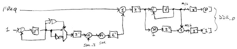
Timing paths go from the clock source, to the launch register, through asynchronous logic and wires, to the latch register.  The worst paths in the timing report were launched from a prescaling counter in the SPDIF component, and latched at the NCO divider (modulo counter) in the pitch and volume axes LC_DPLLs - registers which are internal to the components themselves and not at all brought out to a port, much less connected!

So I checked, double-checked, and triple-checked the explicit and implicit port connections, but found nothing that could account for this.  Then I spent a lot of time trying to get observability into the connection via the various views supplied by the tools - the best I found was by doing a "Report Timing... (In TimeQuest UI)" then right clicking on the path in TimeQuest and doing a "Locate Path..." in the "Technology Map Viewer" which brings up an auto-generated schematic view of the logic as-built by the synthesis and place & route.  It's a rather tricky viewer to navigate in, and the component ports names can be kinda cryptic, but it showed a direct wire going from the prescaler LSb register to the NCO divider LSb register.

Thinking it was a bug in the tool that might be fixed with a later version of Quartus, I searched for the latest version that supports Windows XP and nothing would tell me that, not even the Intel / Altera web page where you download them (!) - but by examining the various chicken entrails and tea leaves, it seems v13.1 is the latest.  Downloaded that and the latest patch, installed and applied the patch, but it generates the same failing paths as the older version I was using (v10.1sp1).  Yarg.

Synthesis of the SystemVerilog code performs a variety of optimizations on the final logical blob that gets presented to the fitter.  These optimizations include the reduction / elimination of redundant asynchronous logic via Karnaugh mapping techniques and the like, and the removal of identical registers, all followed by a mapping to the logic available in the target device.  I realized this morning that the LSb of the NCO divider was always driven by a '1' which makes it toggle at 1/2 the clock rate, and this is the same behavior the SPDIF prescaler LSb performs, so synthesis was mushing them together, causing a timing bottleneck.  Why synthesis is doing this is unknown to me, as the "Timing-Driven Synthesis" option is checked, so one would think that it really ought to know better.  And the fitter settings let it add redundant registers to reduce fan-out and speed things up, so there's not a lot of excuse here for why this is happening.

The solution?  Preset rather than reset the prescale count at initialization!  A one character change in the code after a day and a half snipe hunt.  This rather insidious tooling issue has caused me to lose a bit confidence in the FPGA build process, not to mention causing me to lose a bit of time (and sleep).

Speaking of time, my personal odometer hit 60 yesterday - surreal.  Beats the alternative, I suppose.

Posted: 3/17/2019 3:38:30 PM
dewster

From: Northern NJ, USA

Joined: 2/17/2012

Whither Dither

Taking another look at dither in the LC tank oscillators.  Dithering is adding noise for the purpose of increasing digital resolution.  For instance, when you change the sample size (number of bits of resolution) of recorded audio when mastering a CD, you generally add noise to the least significant bits before chopping them off to 16 bit PCM.  Doing so gives resolution way below the truncation noise floor, which is counter intuitive.  It's actually a form of conservation of energy, only violated over a short time frame. If over the longer term the energy isn't lost, but is transferred to the next stage, then all kinds of good things happen.

What I've been doing up until now is generating pseudo random noise, adding that to the output of the NCO (numerically controlled oscillator), then chopping all the bits except for the MSb (most significant bit) off to form the output square wave that stimulates the LC tank.  For the longest time I thought it would be best to push as much of the noise energy up into the higher frequencies, so as to make it easier to filter out afterward.  My latest NCO performed a double differentiation to tilt the noise up on the high frequency end and down on the low frequency end, but I wasn't seeing a lot of dither making it to the other side of the tank at the C divider, where it is needed at the FPGA quadrature input to resolve sub-clock intervals.  This makes sense because the LC is a (very peaky) second order lowpass filter, and the double differentiation is kicking much of the noise energy above the LC cutoff.  The dither unfortunately is not similarly filtered at the FPGA zero input, and the phase detector can be thought of as a differential input for phase noise, so all I'm doing is adding noise to the signal, not useful dither.  We want more of a common mode noise situation where the dither makes it to both the FPGA quadrature and zero inputs.

To replace the pseudo random noise source, I coded up a triangle waveform generator in SV that has a cycle time of 48kHz.  A triangle wave has most of its energy in the fundamental, and has a rectangular PDF (probability density function) like the noise it's replacing.  However, a triangle wave is rhythmic, and 48kHz is the same as the software sampling rate, so any rhythmic perturbation happening at the sampling rate should effectively have a zero in the response - this dither in a way is common mode in the time domain.  48kHz happens to be roughly two decades below the LC resonance point, as well as roughly two decades above the LC_DPLL low-pass cutoff, which is interesting.  Two decades above the LC_DPLL means any residual will be attenuated by approximately 40dB.  The new NCO is now substantially simpler, as the frequency input is being dithered rather than the instantaneous phase:

At the lower left is the triangle generator, which turns an unsigned ramp into a signed triangle by XORing the top two ramp bits and using this to select the normal or inverted lower bits.  This is registered for speed, barrel shifted (panel knob), shifted again to adjust the base gain (calculated via parameter math), and added to the input frequency (coming from the DPLL phase accumulator).  This is registered and modulo accumulated at the top right to form the heart of the NCO.  Below this 1/2 of the dithered frequency is added to the accumulated value to give us the next half clock of accumulation.  The MSb's of these are fed to the DDR (dual data rate) inputs at the FPGA output pin in order to give us an effective ~400MHz edge rate.  The higher the edge rate the lower the dither amplitude needs to be.

Testing it, I can jitter the crap out of it and not see the noise floor rise at all, which is really great because there is no obvious downside or trade-off to setting it as high as necessary.  I was hoping for more jitter making its way through the LC but it seems the high Q flywheel action really attenuates it.   I'm wondering if maybe the tank Q should be reduced / controlled, as it limits the influence of the dither?  This would be simply inserting a series resistor in the coil drive (and adjusting the C divider values to accommodate the lower antenna swing).  The dither knob goes from 0 to 7, and in my limited testing yesterday and today it seems I can pretty much kill the sticky spots with settings 5 or 6.  Setting 7 starts to reduce the antenna V swing as the tank bobbles around.

I wonder to what extreme this could be taken?  Like lower the Q to 2 and dither like crazy over a 2:1 ratio?  The tank drive voltage would probably have to be raised though, as the Q voltage boost would be quite small.  Spreading the spectra way out might allow both antennas to be tuned the same, as long as the dithers were uncorrelated over the period (maybe have the volume triangle dither run at 2x the rate of the pitch side) - kind of a stone age CDMA (code division multiple access). 

Posted: 3/18/2019 10:30:34 PM
dewster

From: Northern NJ, USA

Joined: 2/17/2012

Spread 'Em!

Some LED tuner driver logic work, removed the prescaler that clocked the interconnect at a fixed 11.25MHz and made it accept an an enable input.  Then made a parameterized pulse generator that kicks out pulses spaced in a pseudo random fashion to enable it, which spreads the tuner interconnect spectra. I also lowered the data rate by 4x, which should help with signal integrity in longer cabling, though this puts the lowest harmonic around 1.4MHz with it spreading up into the pitch and volume field ranges.  If that obviously perturbs anything I can easily move it higher.  


Above is the stochastic pulse generator.  It is enabled by the busy indicator coming from the LED tuner (itself enabled via a write to the HIVE tuner register by software at a 48kHz rate).  A small down counter limits the number of LFSR (linear feedback shift register) shifts to those needed, an offset (MIN) is added to establish the minimum inter-pulse distance, and this is loaded into another down counter which generates a pulse when it hits zero.

An interesting thing about this process is that when doing a data transfer (which contains either 50 or 56 edges depending on the mode), it's adding together many random delays.  A single LFSR delay gives you a rectangular PDF (probability density function), where all possible delays have the same probability.  Two of these delays added together give you a triangular PDF which linearly tapers up to the median and back down.  And anything over around 5 delays added together gives a Gaussian shaped PDF, which favors the median and heavily disfavors outliers.  So the total time of the data transfers is more or less statistically contained to the median and small-ish deviations from it.  This is good because we're doing PWM (pulse width modulation) of the LEDs to provide grayscale, and with the now lowered data rate, the data transfer consumes a majority of the PWM interval (1/48kHz), so excessive variability here could show up as unwanted flickering.

I've currently got it set to a 2:1 ratio, spreading the holy heck out of the signals. With this I believe the overall design is largely tapped out in terms of reducing internal emissions / interactions via logical tricks (i.e. I've limited LCD writes to only those necessary, and the 8 thread interrupts are evenly spaced in time).

Posted: 3/20/2019 8:23:19 PM
dewster

From: Northern NJ, USA

Joined: 2/17/2012

Higher F And Much Smaller L - Too Much Of A Good Thing?

Unless you're going for the Tesla coil look (which in itself can be a thing of beauty) you usually want your Theremin coils to be small-ish so that they fit into whatever cabinetry you choose.  You often don't want the coil dimensions dictating your overall cabinet dimensions.  If super high Q and super low self-C aren't issues, and if you don't mind some thermal drift, then ferrite is your man.  Otherwise you're looking at single layer air core inductors, which can be large, so what to do?  If you aren't heterodyning, or if you are heterodyning with dividers in the mix, then you can go to higher LC resonant frequencies and dramatically shrink the inductors.  Since LC frequency is inversely proportional to the square root of the inductance, every doubling of the LC frequency shrinks the inductor value by a factor of 4.  Every decade increase in the LC frequency shrinks the inductor value by 100!  What are the practical limits to this?

Lately I switched the D-Lev prototype to the quite small (by Theremin standards) inductances of 0.5mH on the pitch axis and 0.25mH on the volume axis.  It seems that grounding became more of an issue with the use of these smaller inductors, which isn't surprising I suppose, as ground wires start acting more like inductors at higher frequencies, and the Theremin is understandably quite sensitive to grounding issues.  The Theremin acts kind of like a transformer, with low impedance and low voltages on the ground side, and high impedance and high voltage on the antenna side.  Roger discovered that small voltage perturbations on the ground side translate into large perturbations overall, and this could very well be an interesting and convenient method to measure the gestural bandwidth of a high Q Theremin.

Anyway, I decided to look into this.  I removed the volume axis coil and temporarily installed, one at a time, a variety of coils I had laying around the casa del dewster cutting edge high tech Theremin laboratory / laundry room, and measured the noise / hum amplitude given different powering and grounding.  

I powered the prototype two ways: 1) via USB from my PC which provides a ground, and 2) via an Amazon Fire wall-wart which doesn't supply a ground.  I provided up to three grounds:  1) via the USB on my PC, 2) via a heavy AC ground wire going to a wall socket adjacent to the one my PC is plugged into, and 3) via the scope ground from one of the probes of my brand spankin' new Rigol 1054Z (sweet!). 

The volume axis in the FPGA LC DPLL was set to 280Hz bandwidth @ 2600kHz LC resonance, with a 4th order lowpass @ 415Hz.  DPLL loop bandwidth is inversely proportional to LC resonance, so this is arguably a negligible gain factor for the hum as the BW for the noise is already ~2/3 of the 4th order bandwidth, which ultimately limits it.  And these measurements are pretty rough anyway.

The hum amplitude was recorded in Adobe Audition with constant though arbitrary analog gain setting, using a special diagnostic software load.

Above: plotted data for hum vs. inductor value.  For the 1,2,3 ground chart series the USB and Fire powering with AC ground are averaged (1 ground), as are the USB with AC ground and Fire with AC and scope grounding (2 grounds).

It seems clear (if my data is any good) that above below 1mH grounding becomes much more critical and touchy.  For this reason I've currently got 1mH on the pitch side and 2mH on the volume side.  Maybe I should have graphed hum vs. operating frequency, as it's likely the frequency of the ground currents at work here?  Also, I'm calling it "hum" but it's really mains hum plus noise, with the hum generally dominating.

While performing this testing, I ran into some trouble with the DPLL locking at start-up: the NCO was diving way down into the 10's of kHz and staying there for long periods until eventually locking correctly.  So I added a parameterized lower limit to the phase error accumulator, set it to a 16:1 range (way more than enough for anything), and that seems to have done the trick as I didn't see it misbehave again through all of my testing.  Evidence of absence isn't proof of absence, but it's something, and that extreme low end is really difficult for the XOR phase detector, and particularly for the C divider, to function at.

Posted: 3/21/2019 1:37:11 PM
dewster

From: Northern NJ, USA

Joined: 2/17/2012

"Maybe I should have graphed hum vs. operating frequency..."

Above is the data from my previous post plotted log amplitude vs. LC resonant frequency.  Due to the dearth and lumpiness of the data, it's difficult to draw firm conclusions, but it generally looks more linear in this view.  Log amplitude means there are diminishing returns associated with decreasing the LC frequency (increasing the coil inductance), but what is "good enough" for all performance situations?  A lot of times the unit will probably be on the other end of a 100' (30m) or more extension cord when on stage.  The longest ground wire I tested was around 8' (2.5m).

Above is just the Fire wall-wart data.  It seems to imply that at around 1MHz the added grounding has no effect, and with differential influence above and below this point.

Above is just the USB powered data.  It also seems to imply that at around 1MHz the added grounding has no effect, but with common influence above and below this point.

I don't know what to make of the huge bump around 1MHz (2mH inductor).  I took the data twice and it showed up both times.  Perhaps I should be using an automated RMS measure of the hum & noise, rather than eyeballing the peaks.

[EDIT] So I just used the RMS Average measure in Adobe Audition and the graphs look quite similar to the peak eyeball graphs above.  The RMS graphs track better together below 2mH, so the differential / common observation above is seems moot.

If one is being extra careful about the design of one's digital Theremin, the data trend seems to be saying that the inductors should be as large as possible, such as 2mH and 4mH, or 4mH and 8mH.  Ideally, I think one would stick the larger inductor on the pitch axis to keep noise & hum to a minimum where it would be most easily perceived.  But then placing one's hand directly on an uninsulated volume antenna could bring it too close to the pitch operating point, causing interference.  IMO uninsulated antennas don't make a lot of sense for any Theremin.

Posted: 3/22/2019 2:51:25 PM
dewster

From: Northern NJ, USA

Joined: 2/17/2012

Plates vs. Rod & Loop - A Poll!

I've found the plate antennas on the D-Lev to be really easy to play, and am wondering what readers here think of them.

A plate has more surface area than a small diameter rod, and therefore makes a better "half capacitor," with the hand forming the other half.  For this reason I'm partial to them from an engineering perspective, as they increase absolute sensitivity.

For the volume side, a plate isn't all that different from a standard loop.  You obviously can't put your fingers through the middle of a plate, nor hang onto it to shut it up (though I use reversed sense so I wouldn't do that anyway), but with the programmable knee there isn't any need to actually get all that close to it - my hand is never closer than maybe 6".  And you generally don't want to touch the thing anyway as it disturbs the pitch side by getting the whole thing rocking for a bit, not to mention ESD.

On the pitch side, the width of the plate makes for an easier soft target.  I don't need to constantly have the pitch plate within eyeshot in order to have my hand address it sufficiently on center to play (which is good because I'm watching the LED tuner like a hawk!).

But boy, are plates a bear when it comes to functional and attractive enclosures for them!  The volume plate is horizontal, so it can fairly easily be integrated into the top, or top and side, of a total slab-like enclosure.  But the pitch plate needs to be farther away, more vertical, and oriented towards the player's head, which forms a compound angle that's difficult to integrate into an enclosure formed of right angles (I'm having to deal with these same issues for the control box).  Bending the plate into a 'U' as I have done and locating the coil behind it allows for a compact cubic enclosure for the whole thing, but then you've got ball joints and (worse) exposed cabling to deal with (though I could locate the coil in the main enclosure).  

Perhaps one way to have one's cake and eat it too is to make the pitch antenna a hybrid of sorts - a cylinder.  The diameter of the cylinder could allow for adequate conductive area, and the isomorphism about the vertical axis would preclude the need to rotate it.  It would be a tougher target to hit horizontally without looking, which is my main gripe.  Perhaps both antennas could be horizontal cylinders?  Or the pitch antenna a sphere?

For some sizing based on the (somewhat arbitrary) surface area of my current plates, which are 0.3m x 0.15m = 0.045m^2:

Cylinder: 0.047m diameter x 0.30m long
Cylinder: 0.057m diameter x 0.25m long
Cylinder: 0.071m diameter x 0.20m long
Sphere: 0.12m diameter

It's interesting that the sphere is close to the volume of a closed fist - smaller than I expected.

What are your thoughts & ideas, dear readers?*

* I'm finding that all sorts of antenna geometries can be adequately linearized on the D-Lev, so don't let that be a concern in your response.

Posted: 3/22/2019 5:10:46 PM
pitts8rh

From: Minnesota USA

Joined: 11/27/2015

I'll start off stuffing the ballot box by placing 5 votes for a conventional 3/8" x 23.5" pitch rod and an Etherwave-size 3/8" diameter volume loop.  Both work great, and none of the dimensions seem critical.

Make that 10 votes...

Posted: 3/22/2019 6:04:27 PM
tinkeringdude

From: Germany

Joined: 8/30/2014

Could the pitch plate not be in some plastic-y, rubbery, whatever tight-fit enclosure (maybe disc shaped for nicer look? eye of the beholder...), and held at needed distance and angle with some "fastening wheels" and joints like mic stands have them...
Would it be so bad if the whole setup looked just very slightly drum kit like? (with rods at angles, holding stuff towards the player - just, maybe, non-conducting ones in this case, and some thin cable for low capacity connects to a jack at the device base...)

Posted: 3/23/2019 1:11:25 PM
dewster

From: Northern NJ, USA

Joined: 2/17/2012

"I'll start off stuffing the ballot box by placing 5 votes for a conventional 3/8" x 23.5" pitch rod and an Etherwave-size 3/8" diameter volume loop." - pitts8rh

The design space I find myself in with plates is analogous to those who create synthesis controllers based on acoustic instruments.  On one hand, one wants to leverage the all the familiarity one can of the large installed base players who learned on the "real" thing.  They'll likely be the biggest initial consumer group so one logically should go out of one's way in order to accommodate and please them.  On the other hand, many of the "form-follows-function" reasons for the original simply vanish for the synth controller, so how constrained / freed should the designer feel or behave in terms of fidelity to legacy?  E.g. if you're designing a guitar controller do you make the "fret" spacing linear now that you don't have to make it logarithmic (for the strings)?  Do you make the neck straight now that you don't have to taper it (for the strings)?  I mean, you very much want to change these things because they free the player from having to adapt themselves to the vagaries of the instrument.  Exactly which legacy features are good to retain are a series of judgement calls, unfortunately.  (As an engineer I've developed a rather visceral reaction to legacy and I'm trying my best to keep that at bay! :-)

I know it sounds pretentious and foolish, but I'd like to do my part to relax the learning curve for the next crop of Theremin players.  And this means, for better or for worse, influencing / altering how they learn to play the Theremin.  User variable linear note spacing is probably the largest part of this.  I don't think many would argue that linearity of the entire field is a good goal, even though it removes a prominent playing response common to all conventional Theremins.  Theremin and Moog were almost certainly doing whatever they could (with what they had at the time) to linearize the pitch field.  And user variable note spacing frees the player to use whatever hand / fingering style that works best for them (wider settings enable other minor things like breathing and not having to stand like a statue). Data point of one, but I wouldn't have bothered to learn the Theremin without this feature as it is so central to playablility for me.  Larger note spacing profoundly alters the playing experience in a very fundamental way - it's like going from a mandolin to a classical guitar.

In my mind plates are part of this.  A long thin pitch rod is there on analog Theremins for very good engineering reasons as it helps to linearize the field somewhat.  Once that pressure is removed, can we do better?  And if we can, why not?  I'm sure that there are players who depend, however consciously, on the geometry a thin pitch rod imparts to the near field for their playing style (I'm looking at you Roger! :-).  Nothing personal, but how much should such players be accommodated when the slate is clean?  I mean, if they've already accommodated themselves and their playing style to rigid demands of one form of the instrument, is it too much to ask them to adapt a bit to another?  Though I imagine it could seem like feature removal to them.

One thing that often stands out to me when watching videos of public Theremin performances is the Steve Martin "disappearing dime trick for those in the back row" effect - traditional antennas are so thin it often isn't at all obvious what is being addressed by the player's hands, thus minimizing much of the dramatic effect ("why's that guy waving his hands around?" or "why is that girl standing so still and moving her fingers?").  Plates or larger diameter tubes would be much clearer in this respect.

I suppose one should at least offer the option of conventional rod & loop antennas, but honestly they feel like a step forward missed.  I probably shouldn't be so adamant about it though, and I hope no one thinks I'm attacking them personally over this.

==================

"Would it be so bad if the whole setup looked just very slightly drum kit like?" - tinkeringdude

Interesting idea, thanks!  Now that I think about it, that's kind of what my prototype looks like at the moment, a crossbar on a mic stand, "drum heads" on wires going to a "brain."  There's all this air between the controller and the plates that I'm rather loathe to enclose in heavy wood and such as that impacts portability.  A very minimalistic and lightweight digital drum-like stand would also help with tipping issues - I wonder how many Theremins have bit the dust after being knocked over?  Though drum stands are rigid because someone's literally beating on them, whereas Theremin play couldn't be more of the exact opposite!

Posted: 3/23/2019 7:02:01 PM
dewster

From: Northern NJ, USA

Joined: 2/17/2012

Cases Qua Cases

I've probably said this before, but one thing I'm really drawn to is electronics enclosures that double as shipping cases.  I think people have lower aesthetic expectations when it comes to this sort of thing, so maybe some sort of thinner wood like flake board with internally braced corners, covered in rat fur or crackle finish paint, with external corner protectors? 

I've looked around but I don't see any off-the-shelf offerings that have removable tops and internal panel mounting brackets.  Otherwise, things that look dimensionally reasonable either are - or strongly resemble - rifle cases, and I'm not sure how many people want to walk around in public (or an airport!) with something like that!  And plastic cases tend to be pretty heavy, so they come with wheels and handles and such, which ironically makes them even heavier.

I've drawn the required prototype dimensions out on paper, and the thing is so spaced out and 3D I really don't have any idea as to how it might fit in any kind of case.  I've banged my head against this particular wall many times.

You must be logged in to post a reply. Please log in or register for a new account.