Let's Design and Build a (mostly) Digital Theremin!

Posted: 2/21/2020 8:34:04 PM
dewster

From: Northern NJ, USA

Joined: 2/17/2012

D-Lev Prototype II

I swore to Roger (and myself) that I'd finally get around to using the beautiful boards he so generously sent me ages ago.  Today's the day!  Well, a couple of days ago were the day!  Whenst I purchased an enclosure to expand my "Tupperware party" - but today it's actually falling together.

It began in the usual way, a search for "plastic box" on Amazon, eBay, Google, Duck duck go, etc. which resulted in pretty much nothing, so it ended as usual too.  I wanted a main box that was longer than the one the first prototype is built in (which is a shoe box really) but everything that was longer was waaaay longer, like a meter or more, designed to hold rolls of holiday wrapping paper and the like.  Boxes that were just somewhat longer than a shoe box were wider as well, which I wasn't really looking for, but in the end I decided to take this baby home for a cool $3 USD or so:

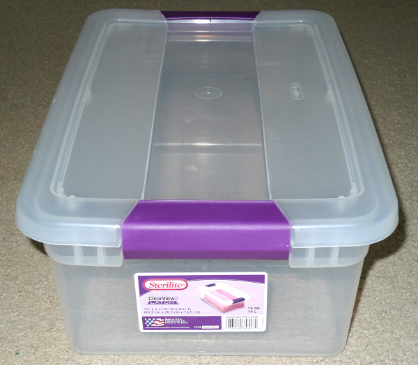
It's a 15 Qt / 14 L "clear" (milky really) storage container from Sterilite, UPC 073149753175, made in the US of A.  It says the dimensions are 17" x 11 1/8" by 6 1/2" (432mm x 283mm x 165mm).  Gotta have the "clear" to easily mount things that display without cutting holes.

Prototyping enclosures should be "beautifully ugly" and inexpensive so you have zero qualms about drilling a hole here or there, and zero qualms about abandoning those holes, or even the entire box, when you feel the need to try something else out.  If the enclosure is too expensive or too pretty or too close to the finished product, you will necessarily think ten times about drilling a hole, and wince when you finally screw up the courage to do it, and ergonomic experimentation (and perhaps the entire project) will grind to a halt.  Ideal prototyping enclosures make terrible show-and-tell subjects (and I feel a little bad showing them to the world like this) but they're really not intended for that.  They're just there to cheaply hold all the stuff together and that's it.  Anything more and it just gets in your way.

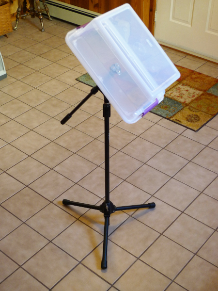
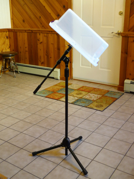
The lid on this comes entirely off, and that's where I'm going to mount the mike stand flange, and the whole thing will then be upside down.  You want a removable lid rather than a hinged lid, otherwise you'll be fighting it and having it flop around when you're inside trying to work on the innards.

I dug Roger's boards out, hooked up the tuner and encoders, and hooked the main board up to a USB serial cable which also supplies 5V.

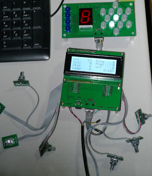
Et voila!  It's alive!  That was too easy (because Roger did all the work).  I pumped it up with the very latest software load via the librarian software, but still need to update the FPGA load as well to get the new dither logic working. 

The LCD is really, really bright, much brighter than the LCD backlight on my first prototype.  I adjusted the LCD contrast trimmer and it looks fine and all, but I can't seem to get that "you've gone too far" region where the off pixels are turning on - both ends of the adjustment are washed out.  The contrast pot has 3.3V across it, hmm.

The encoders seem much more positive than the ones on my first prototype, though maybe some of that is them loosening up over time with use?  These things aren't rated for a very long a life.  But these are really crisp feeling and definite in their action.

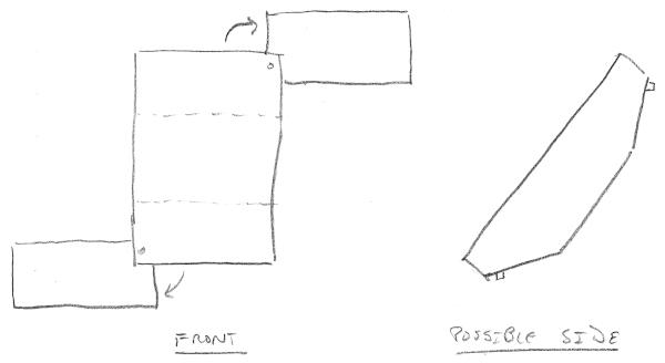
I wasn't looking for wider box, but it might be interesting to have the bases of the antennas start out farther apart, and have more room inside and area on the control panel for speakers and such.  It's funny how many things housing dictates with an iron fist, even the imagination.  I plan to first try coils inside with paddle plates.  Due to a lack of height in this box, I think the tuner will be going in a separate enclosure on the top, probably a sandwich container (why stop now?).

Anyway, this one should be much more robust, and therefore able to travel better.  My first prototype is fairly fragile so I've never really taken it anywhere, not even upstairs to the music room.

Posted: 2/22/2020 2:57:13 PM
Buggins

From: Porto, Portugal

Joined: 3/16/2017

To Heterodyne, Or Not To HeterodyneVadim (Buggins) over on his Teensy 4.0 600MHz ARM Cortex M-7 MCU - ideal for digital MCU based theremin? thread is describing methods to best capture the pitch axis information in the highest resolution / SNR way possible with an inexpensive processor.  This is a laudable goal and I'm not trying to discourage it nor disparage it in any way, though I do have some thoughts about it because I was going down a similar (though not identical) path a while back, so I have performed a fair amount of research, and even had some pretty clean FPGA code ready to go, before ultimately abandoning it for various reasons.  I'm not saying I'm an expert on the subject, and it's entirely possible that I've missed some vital path that makes it more tractable and attractive, but I want to yak about it a bit.Heterodyning is the non-linear mixing of two frequencies, producing new frequencies that are additions and subtractions of the input frequencies, and in this case (as in the case of the analog Theremin) we are interested in the subtraction frequency.  The pros of heterodyning are quite clear for a purely processor based Theremin, and indeed this is why you see heterodyning implemented on the Open.Theremin - it's really the only game in town when you don't have a way to precisely produce frequencies, nor the means to precisely measure them.  A D flip-flop or XOR and low pass filter is used to perform the heterodyning, with the result sent to the processor for period measurement. Earlier versions of the Open.Theremin employed the latter, and the latest version employs the former.A general issue here is the generation of the fixed frequency to heterodyne the variable frequency with.  If we don't have precise control over this frequency then we need to be able to offset the variable oscillator by tuning it, and this is the approach the Open.Theremin takes.  The obvious problem with this is it requires a touchy analog adjustment on a (mostly) digital instrument which could be avoided entirely if the fixed oscillator were adequately controllable via digital generation.  But it is a simple approach, and if you gotta do it, you gotta do it.The super nice thing about using a D flip-flop as the detector is it removes the high frequency heterodyne content and gives the processor a nice square signal to measure.  The problem with using a D flip-flop is the edges of the heterodyne result can only happen on the D clock rising edge, which quantizes the period being measured.  The introduction of dither (phase modulation) could help to break up the quantization, but I'm not sure how one might introduce this in a processor setting.  One could also perhaps use two flops here to double the resolution / halve the quantization error, but the measuring logic would have to be able to utilize this info in order for it to be actually useful.The nice thing about using an XOR gate as a detector is you can get analog like precision timing from it.  But the main snag is properly filtering out the high frequency components.  You need a high order, very low Q low-pass filter to do this, and there are many problematic issues associated with this structure.  You want just the difference frequency, but unless you are careful some higher frequency content will get through.  If the higher frequency content is too strong you will get ripples, which will give you trouble when you go to square up the result.  You want it to work over a really wide range but it really attenuates at higher frequencies, so the difference frequency will be quite small in amplitude when the difference is large, which can again lead to thresholding problems when squaring it up.  The ideal situation here would be to have a tracking low-pass filter admitting only the difference frequency and killing those above, but that would be really difficult to implement in the analog domain, and it might get into troublesome modes, as you are filtering the thing that is telling you where to set the filter cutoff frequency, forming a control feedback loop.Another general issue is that you are averaging periods, and because the periods themselves are happening at a different rate than the rate that you are sampling them at in the larger scheme of things, you essentially have a variable multi-rate process going on.  I spent a lot of time looking at this and it is by no means a simple scenario.  The best solution I think is to vary the averaging rate, which is best done via high order low pass filtering so we are varying the cutoff frequency, with the inverse of the length of the period (i.e. the frequency) - and indeed this is something I do on the D-Lev, though with the PLL frequency number.Another general issue is the lag problem when measuring lower frequencies.  So you are perhaps best to limit the lowest heterodyned frequency result, which implies offset heterodyning.  If you carefully engineer offset heterodying with period measurement you can improve the pitch field linearity, and indeed this is actually the main reason I was pursuing heterodyning in the first place.  But this inextricably ties together a lot of stuff that's much easier to deal with separately.Another nice thing about heterodyning with period measurement is it gives you higher resolution in the far-field, and adequate resolution in the near-field.  But I've found that, ultimately, the far field not that useful for playing purposes.  Regardless of the method used, analog or digital, the far-field is fairly unstable and difficult to calibrate for linearity (via the null control) as the rest of the body has a lot of influence over it, so I find myself avoiding it when playing.  My body probably moved a little since I did the acal, the electronics may have drifted a bit, etc. - so I can't trust the linearity out there.  Even analog Thereminists will know what I'm talking about here.So there's my brain dump from my hazy recollection of what I was looking into years ago.  If I were trying to do an MCU based digital Theremin I might first try to rule in/out the D flip-flop approach, but unless I was really cheaping down I wouldn't go the analog tuning route, as that makes everything too touchy.  If one is instituting some form of crystal or ceramic oscillator for the reference frequency, you might as well use the money and board space to instead install a PLL solution here (tapping off the processor crystal), with fine control via SPI or I2C.  And if you're doing that, maybe a cheap FPGA instead, with the processor inside, etc. - and you're on a slippery slope with something like the D-Lev at the bottom.[EDIT] We are all playing games in a way depending on the platform we choose to implement a digital Theremin, and Vadim is doing this more explicitly with his project, i.e. limiting himself to the resources available in a particular MCU.  Ultimately, it all comes down to the precision with which we can generate, and particularly the precision with which we can measure, timing.  If thermal noise is the determining factor in all of this then we have adequately precise timing or better.  If we're close, then dither and averaging can help bridge the gap.  If we're miles away then we have to find some other means to generate timing, and then somehow measure slower products of that (i.e. have external processes improve the precision to the point where we can throw some of it away).

I believe I've finally found solution for Teensy 4 MCU, w/o any external hardware (except oscillators), w/o heterodyne, better sensitive than heterodyne.
Latency 2ms (including 1ms audio IO frame), and sensitivity <1mm at 100cm distance from antenna (for single 1ms measure, no inter-frame averaging).

Posted: 2/22/2020 7:19:26 PM
dewster

From: Northern NJ, USA

Joined: 2/17/2012

To CIC, Or Not To CIC

"I believe I've finally found solution for Teensy 4 MCU, w/o any external hardware (except oscillators), w/o heterodyne, better sensitive than heterodyne.  Latency 2ms (including 1ms audio IO frame), and sensitivity <1mm at 100cm distance from antenna (for single 1ms measure, no inter-frame averaging)."  - Buggins

My reply is here: [LINK]

I believe what you are describing is a CIC (Cascade of Integrators & Combs) filter, which is an efficient implementation of the boxcar, or integrate-and-dump, filter.

Posted: 2/22/2020 9:00:44 PM
tinkeringdude

From: Germany

Joined: 8/30/2014

OT, not theremin, but digital, and quite awesome: To their piano and e-piano stuff, Moddart now added a pipe organ.
Well, I'm a fan of physical modelling synthesis, vs. just having some gigabytes of samples on your drive, which do not model interactions between components of a complex instrument... I don't now how much that matters for pipe organ, for piano it certainly does.
https://www.youtube.com/watch?v=sGy_ak4dU2s

Posted: 2/23/2020 4:00:46 PM
dewster

From: Northern NJ, USA

Joined: 2/17/2012

"OT, not theremin, but digital, and quite awesome: To their piano and e-piano stuff, Moddart now added a pipe organ.
Well, I'm a fan of physical modelling synthesis, vs. just having some gigabytes of samples on your drive, which do not model interactions between components of a complex instrument... I don't now how much that matters for pipe organ, for piano it certainly does."  - tinkeringdude

As I'm sure you're aware, Modartt started out with Pianoteq, and though the effort was valiant, it took a looong time for it not to sound synthesized, it was in an "uncanny valley" forever.  There's so much interacting in a piano that it makes sense to synthesize some or all of it just to capture that behavior.  With Roland SuperNatural pianos I believe the note beginnings are sampled, and the decays synthesized, and the sympathetic resonance is also synthesized with delays and such.  A Piano World member familiar with SW examined Pianoteq (the code was obfuscated via XOR with a constant IIRC) and discovered samples in there.  This caused a big fuss and I think Modartt finally said the samples weren't of a real piano, but pre-computed (pre-synthesized) hammer sounds to save cycles.  I remember the coder getting some grief over it all (shoot the messenger).

Their Organteq sounds really nice!  Though pipe organs are much more tractable in terms of synthesis, and also highly amenable to simple sampling.  Or a blend.  Modartt probably should have started with the organ and "graduated" to the piano, they might have gained experience and saved themselves years and years of "that sounds fake!" type (valid) criticism.

It's been a long time since I used Pianoteq, but I loved the interface.  It had a MIDI file player, and could render to WAV, so, depending on the quality of the MIDI file (recording real players almost always sounds much more realistic than "note drawing" sequencing) you could do fairly realistic conversions quite easily.

Posted: 2/23/2020 8:22:33 PM
dewster

From: Northern NJ, USA

Joined: 2/17/2012

Swiss Army Case

Yesterday I managed to drill three holes in my new enclosure - and managed to crack the plastic with one! - to affix the microphone mounting flange.  Pix:


My second "Tupperware party" here is mounted on a boom stand (with the boom set as short as possible) to set the angle to what is comfortable.  I've looked around for off-the-shelf angle adapters but, of the few that are out there, none seem all that appropriate for this application.  Boom stands are fairly common, if this ends up being the general solution it wouldn't be the end of the world.  When loosened, the boom section freely rotates, which makes screwing it on much, much easier and much, much less dangerous than, say, screwing an EWS onto a mic stand, thus avoiding the need for a quick release and the like.  The boom also puts the D-Lev & player a bit farther away from the base, thus reducing the chance of kicking the legs or tripping over them.  As you can see the boom really doesn't stick out that much on the other end, and if desired one could dramatically shorten the boom by sawing it down just for this application.

This wider case is unexpectedly putting ideas in my head.  One brainwave I got last night was to have the plate antennas flush with the back when closed, swinging out on a corner pivot to give it them even more clearance and distance:

The back might even be given a prism profile to better angle the plates for play.  It would look pretty slick, and the manufacturability might not be too much to handle.  An alternative here would be a standard rectangular profile with the plate corners fitting into angled kerfs, storing them in the lid as opposed to swinging out off the back.

Posted: 2/23/2020 10:04:00 PM
tinkeringdude

From: Germany

Joined: 8/30/2014

.A Piano World member familiar with SW examined Pianoteq (the code was obfuscated via XOR with a constant IIRC) and discovered samples in there.  This caused a big fuss and I think Modartt finally said the samples weren't of a real piano, but pre-computed (pre-synthesized) hammer sounds to save cycles.

Well, in those few MB of an installation, and considering how good it sounds, what could possibly be in there wrt samples that would be anywhere near scandalous? Nothing. Precomputed tables for hammer sounds seems plausible, those are probably the most static, short and least noticeable (in detail) sounds in the whole mix.
Yeah, it didn't sound entirely realistic in the beginning. Neither do the vast majority of piano sounds on expensive "do some of everything" keyboards, or at least it used to be the case just a couple years ago.

He seems to be happy, and it sounds nice, version 6 anyway. Apparently there is not that much new compared to v5, which has been around for some years.
Roughly at 02:50 he plays a little for demo'ing aspects.
The "SuperNatural" in my "Jupiter 50" does not sound anywhere near as nice... but that product wasn't their most famed effort, apparently, maybe the tech generation was superseded .
https://www.youtube.com/watch?v=j4SEgi5pADA

I also liked their E-piano sounds. Never tried one of the real electromechanical ones for comparison.

I so far with my modest knowledge have only managed to code together a halfway convincing transistor organ, probably the least difficult of them all. My stab at a Hammond (not the Emerson way!) sounds like a cheesy, cheap imitation found in many keyboards, alas

Do you know this Hammond clone where some guy implemented every detail in an FPGA... sounded great, "HX3" it was, I believe.

---
Those tupperware things are probably mean ESD dispensers, eh?

Posted: 2/23/2020 10:31:35 PM
dewster

From: Northern NJ, USA

Joined: 2/17/2012

"Well, in those few MB of an installation, and considering how good it sounds, what could possibly be in there wrt samples that would be anywhere near scandalous?"  - tinkeringdude

Yeah, pretty much nothing, but it was just that Modartt said "absolutely no samples here!" a lot and someone stumbled on something that mildly quacked like samples.  Then (IIRC) they got officially mad at the person for revealing it (is reverse engineering SW a crime?).  Tempest in a teapot I suppose, but things (IIRC) escalated to the point where PW mods yanked the relevant forum post.  It was kinda weird to live through.

"The "SuperNatural" in my "Jupiter 50" does not sound anywhere near as nice..."

The "Studio" piano in our RD-700NX is the best of the lot IMO, not the flagship one they push, which is reportedly an amalgam (read bastard child) of a variety of pianos.  The Studio is clean, on the bright side, and sorta spare, rather Yamaha-ish.

"Do you know this Hammond clone where some guy implemented every detail in an FPGA... sounded great, "HX3" it was, I believe."

Yes, but I appreciate the pointer!

"Those tupperware things are probably mean ESD dispensers, eh?"

Hadn't thought of that!  I have an ESD bleeder built-in to the first prototype, will probably be a permanent fixture on this and any future (hopefully non-Tupperware from here on out) stuff.

Posted: 2/24/2020 2:35:57 PM
dewster

From: Northern NJ, USA

Joined: 2/17/2012

SuperNatural

"The "Studio" piano in our RD-700NX is the best of the lot IMO, not the flagship one they push, which is reportedly an amalgam (read bastard child) of a variety of pianos.  The Studio is clean, on the bright side, and sorta spare, rather Yamaha-ish."  - moi, above

For an up-close example of what the three different SuperNatural pianos in the RD-700NX sound like, years ago I rendered a fantastic MIDI file created by Saya Tomoko of Sati's Gnossiennes: [MP3].  The order is Studio, Brilliant, Concert, with the latter I believe to be the "standard" SN piano Roland sticks in everything, unfortunately.  (It's been downloaded 856 times since I created it!)

You may or may not like the tibre, tone, etc. and it otherwise may not be your sonic cup of tea, but no digital piano at the time could touch Roland's SN for detailed decay.  Everything else was stretched (using the samples of one note for adjacent notes - the natural resonances of the entire piano get transposed too), looped (where the natural decay is chopped off and replaced by a decaying loop - this sounds as bad as it reads), insufficiently layered (not enough sampling of the dynamics of each note), etc.  It's incredible that in this day and age, where 1GB of Flash sells for ~$0.18 USD, we still have massive butchery going on to hack the sample sets of even very high end digital pianos down to almost nothing.  There was a baby somewhere in all that bathwater...

I once did a back-of-the-envelope calculation over on Piano World where I proved there was sufficient bandwidth at the pins of an inexpensive commodity Flash part to do gobs of polyphony with very little RAM.  And the generally incredulous response was that I didn't know what I was talking about, because otherwise we could have absolutely killer, lush, nuanced digital piano voices even in low-end $500 instruments, and my own damn testing showed that there was nothing like that even on the highest end.

Other arguments I had to fend off regularly were of the "the technology doesn't matter, it's how it sounds that counts" variety.  Like someone mailing you a 10kB JPG of some beautiful vacation spot they visited, you know right off the bat just by looking at the file size that it can't possibly look very good, there just isn't enough data there to do it justice. Except with digital pianos the lossy compression they've been employing forever is completely stone age and therefore much more audible compared to the way MP3 operates.  I felt my "job" at Piano World was to evaluate the technology behind it all, and once that was sufficient then discussions about whether it sounded like a Steinway or whatever would be much more relevant.  I had to pepper every little thing I said with disclaimers, and manufacturers development was at least a decade off anywhere near the state of the art, stuck in molasses slow motion, so it just got old at some point.  (Though I must admit that it was a bit of a thrill informing die-hard Yamaha fanboys that their latest top-of-the-line stage piano - AS PLAYED BY SIR ELTON JOHN HIMSELF!  AT NAMM! - was audibly looped.)

Sometimes the very same people who claimed that looping, stretching, poor layering, etc. in their beloved digital piano was effectively inaudible and no big deal would simultaneously have super sensitive golden ears when it came to mild MP3 compression.  Go figure.

I was subjected to so many crappy digital piano voices during the course of my testing that I can hear them coming a mile away and start to break out in hives.  If individual notes sound fake, then chances are extremely good that piling a bunch of them together, even "in a mix", will still be obviously fake.  Unnaturally quick decay to hide loops, and decay processing to kill all the natural "wobble" of 3 strings slowly beating together (again, to hide the loops) are a big tells.

Posted: 2/24/2020 10:54:02 PM
dewster

From: Northern NJ, USA

Joined: 2/17/2012

Whitman's Sampler

Wanted to discuss the Pitch axis filtering / decimation a bit (volume axis is ~identical):

First: the Nyquist limit is simply 1/2 the sample rate, and the sample rate is just the clock rate of a digital filter.  If we try to sample waveforms with frequency components (harmonics) that are above the Nyquist rate, then they will alias downward in frequency, possibly causing havoc.  This is a form of non-linear distortion, and you can't do much about it with filters and such to get rid of it after it has happened, so we want to avoid aliasing if at all possible because it causes permanent degradation.  Aliasing can and will happen every time something is sampled, even when doing innocuous seeming things like generating waveforms, and all we can do is minimize it.

Second: For simplicity, these are back-of-the-envelope 1st order type calculations, but they are actually good enough to do the full design.

The DPLL forms a first order low pass IIR (infinite impulse response, or recursive, equivalent to an RC analog) filter for phase noise, which means it filters out input components that are above a certain cutoff frequency.  The loop gain of the DPLL sets the cutoff frequency, or the frequency above which the filtering starts, and below this there is no filtering action.  The loop gain is an ill-specified parameter, one factor in particular is the LC Q, so we can only estimate the cutoff to be somewhere around 148Hz.  Since it is clocked at 196.67MHz (actually 196.666667MHz) and it uses DDR elements at the I/O, this puts Nyquist at 196.67MHz, so it can effectively filter and reduce incoming noise, RF, etc. all the way up to 196.67MHz.  Above that noise is free to enter and alias.  So it's clear that we want the effective sampling rate of the outside world to be as high as possible for aliasing reasons, as well as for maximum resolution reasons. The output of the DPLL for axis data use is the frequency number into the NCO, which is 32 bits wide.

Next is a first order low pass IIR filter set to a cutoff frequency of 489kHz, and it is also clocked at 196.67MHz.  This filter exists to downsample from 196.67 MHz sample rate to half that, or 98.33MHz, because the following filter can't physically operate at the full clock rate (this is an FPGA speed limitation on very wide addition going on inside the filter).  The following filter is clocked at 98.33MHz, so its Nyquist limit is half this or 49.165MHz.  If we divide this by the filter cutoff of 489kHz we get 100.54, which means there are 2 decades of attenuation at 49.165MHz.  Since filters "roll off" or attenuate at a rate of order * decades * 20dB / decade (or 6dB / octave) we have 1 * 2 * 20dB = 40dB of anti-alias attenuation.  The previous DPLL stage also provides anti-alias attenuation, which is 49.165MHz / 148Hz = 332,195 or 5.5 decades, and 1 * 5.5 * 20dB = 110dB.  40dB + 110dB = 150dB.  Since there are 6dB per bit (bits double the information carrying capacity, and 6dB is a ratio of 2) we have 150 / 6 = 25 bits of attenuation, which is only a little less than our data width of 32, so any aliasing products that are generated by the next filter doing its sampling at 1/2 the rate will be quite small.

Next is a cascade of 4 first order low pass IIR filters set to identical cutoff frequencies of 208Hz and clocked at 98.33MHz.  We want to sample the final output of this cascade at the PCM rate of 48kHz, and hand it off to the software side of things to further filter and then manipulate.  The PCM Nyquist limit is obviously 24kHz, and if we divide this by the filter cutoff frequency of 208Hz we get 115.38.  This is 2 decades, which gives us 4 * 2 * 20dB = 160dB of anti-aliasing attenuation at 24kHz, or 160 / 6 = 26.7 bits, which again protects our 32 bits of data pretty well from the aliasing products of resampling.  In fact, the DPLL also removed 24kHz / 148Hz = 162 or 2.2 decades, 1 * 2.2 * 20dB = 44dB of content at 24kHz, which puts us at 160dB + 24dB = 184dB,  and 184 / 6 = 30 bits, which almost completely covers the data against aliasing at this interface.

The output the 4 filter cascade is latched at 48kHz and sent to a processor register, and the processor pitch axis thread is identically interrupted at 48kHz to retrieve the data.  The data latch gives us a very uniform synchronous sampling period in the filter clock domain, and also serves to eliminate metastability and variable flight time issues (the bits will take different times to cross, so changing vector values can get jumbled) as the data crosses into the processor clock domain.

In software the data is again low pass filtered, this time with a cascade of two second order state variable filters, with the first set to a damping of 2, and the second to a damping of 1.  This provides critical damping (flattest passband) and also keeps the first filter from overloading before the second filter.  The cutoff frequency here is set to 300Hz maximum (250Hz maximum if in a 50Hz mains environment) and modulated downward when the hand is farther from the antenna to improve the signal to noise ratio. 

Following this is a cascade of 6 second order state variable notch filters, which kill the fundamental and first five harmonics of 60Hz mains hum (or optionally 50Hz mains hum).  The individual dampings are roughly adjusted to give roughly flat output between the notches, otherwise the notch skirts would overlap too much at higher frequencies.  You want low damping to kill more hum, but you want high damping to admit more signal - it's a tradeoff.

[EDIT] Errors fixed!

You must be logged in to post a reply. Please log in or register for a new account.