Let's Design and Build a (mostly) Digital Theremin!

Posted: 3/5/2021 2:45:19 PM
pitts8rh

From: Minnesota USA

Joined: 11/27/2015

I think the most recent decoders were a little under $8 each.  If you don't need the box and the connectors it's probably a $2 board, if only you could buy it that way.

The values I had to use for the SPDIF divider were 180 ohm series and 100 shunt in order to get between 0.5 and 0.6v at the inputs (hence the reason I was asking you to confirm the FPGA drive current limits).

Originally I calculated the divider to give the correct voltage with a 75ohm input while also presenting approximately 75 ohms source impedance.  But then I forgot that I have two decoders in parallel.  And then it turned out that they weren't 75 ohms each, but 50. 

So now we have a limited source going to a simple resistor divider with a source Z of 65 ohms. This in turn is feeding about 10" of 110ohm ribbon cable which is ultimately terminated in 25ohms (or so it would seem). Pretty ugly if you are trying to pass broadband waveforms.  Fortunately the moderate rise times and short line length means that the incident and reflections are pretty much coincident and this remains more of a simple resistor division problem than a transmission line nightmare, and the leading edges of the eye pattern as it turns out aren't that ugly. Homely, but not ugly. And in fact the decoder's DC resistance does not appear to accurately represent the signal impedance, because the the 180/100 ohm values above give about 0.55volts on my system when it would seem that it should be lower.

With no room and no real desire to put a proper line driver on the main board, and mismatches galore, we strive forward....

Posted: 3/5/2021 9:20:08 PM
dewster

From: Northern NJ, USA

Joined: 2/17/2012

"The values I had to use for the SPDIF divider were 180 ohm series and 100 shunt in order to get between 0.5 and 0.6v at the inputs (hence the reason I was asking you to confirm the FPGA drive current limits)." - pitts8rh

Ah yes, I'm an idiot, the 0.5Vpp to 0.6Vpp spec is on the wire plugged in, not driving air.

My spreadsheet tells me that 200 ohms series and 120 ohms to ground would work well.  This gives 0.6Vpp for 75 ohm RX and 0.5Vpp for 50 ohm RX.  And it looks like 75 ohms driving the cable.  All assuming infinite current drive.  If we knew who made the IC we could get a datasheet and see what the RX margin is.

Posted: 3/6/2021 12:56:05 AM
pitts8rh

From: Minnesota USA

Joined: 11/27/2015

I think if this was transmission line problem you would want Zsource to be closer to 110ohms.  But then at the other end you would have Zs/Zl = 110/~35 (where 35 ohms appears to be the AC input Z) at the input of the decoders, not a great match.  It sort of goes against my grain to be dismissive of transmission lines effects and matching, but considering the line length, the limited drive current, and the fact that the ultimate load impedance is so low, I'm going to be a little dismissive.  On paper it's not going to look good without introducing a driver.  The fact is I don't think one is needed needed unless you want to be able to pick and choose using one or both decoders on the theremin.

With this short length of line I'm comfortable with ignoring the transmission line and mismatches at the source and load planes (10" remember) and looking at it as a simple resistor division - make the input voltages correct with two parallel (and uncertain) decoder input impedances and stay within the current drive limits. 180/100 gives a good voltage; 200/120 will still work but the voltage will be on the low side with two of these new decoders.

With this short cable run we could just strip the input resistors of the decoders, or replace them with something like 100ohm, but I think they are 603s and I don't want to do those anymore.   

Posted: 3/7/2021 2:46:46 PM
dewster

From: Northern NJ, USA

Joined: 2/17/2012

Turn! Turn! Turn!

The velocity based encoder modulo fence jumping feature turned out to be a bust, so it's been removed.  To do it right one probably needs a separate velocity mechanism, and I just don't think it's worth all that.  The only knob I sorta miss it this on is the UI screen selector - it was nice to be able to easily flick between the main page and the system page.  But having to take a running start in order to hit a stop was just too fiddly the way I had it implemented.

While I was in there I also found myself re-addressed the encoder software "debouncing" (sometimes cryptic code works out: you have to work your way all through it before you figure out what the hell you were thinking, placing you in an ideal position to fix it).  It's not really debouncing, but a throttling of the data rate.  Since velocity is how many knob detents are seen over an interval of time (crudely put, the actual mechanism is more complex) then limiting single detents to some minimum time will limit the mayhem a glitchy encoder can produce downstream in the velocity detector.  I was using a mass stability debounce construct here, much like the subroutine used to mass debounce the pushbuttons, where any input change resets a counter, and the output is only updated when the counter times out.  The problem with this approach as applied to encoders is that any input change will resest the timer, so a series of glitches will just keep resetting it, producing no output, and indeed I saw exactly this happening all the time with the two absolutely horrid encoders on P3 (sometimes flaky hardware works out: you get to address wear and tear in the lab where you can instrument it and try a bunch of stuff, rather than in the field or via the reputational black eye of customer returns).  A better solution here is to take the encoder detent and immediately pass it to the output, reset the counter, and ignore all input until timeout.  And this is now working pretty great.  You literally can't do too much signal massaging/conditioning when it comes to encoder inputs, but some approaches/techniques are inherently superior at handling their criminally insane behavior than others.

Along these lines I also monkeyed with the GPIO debouncing.  The stability debouncing is now bimodal, so I've got it reacting to an active input after 25ms of stability, and reacting to an inactive input after 250ms.  This should reduce the incidence of "retriggering" when toggling audio mute via an external pushbutton.  The mute function itself has been significantly simplified so that the code is the only state keeper, and this also significantly simplifies inputs because they don't have to maintain state, and as many normally open inputs as you like can be wired in parallel.  Give everyone in the audience a mute button and see what they really think about your performance! .

=========

"With this short cable run we could just strip the input resistors of the decoders, or replace them with something like 100ohm, but I think they are 603s and I don't want to do those anymore."  - pitts8rh

I perused some random DAC datasheets yesterday and saw nothing (absence of evidence...) in terms of electrical absolute maximum limits on the SPDIF inputs (though many had stricter limits for the XTAL pins).  I'm betting the SPDIF inputs are just internally biased inverters, and you could blast them with full logic levels without harm (that's the way I would design them anyway).  There is/was an unofficial logic level SPDIF interface used on CD drives that I imagine one would want to stay compatible with too.

The D-Lev AFE digital interfaces seem to work well with 100 ohm series at the drive and nothing on the receive end, are similarly up there in terms of frequency (~1MHz), and if anything are likely more sensitive to perturbation than SPDIF.  I think they're just trying to best ensure 25' runs over sketchy audio cabling with the I/O spec. which is way overkill for significantly shorter runs.

Posted: 3/7/2021 3:34:11 PM
pitts8rh

From: Minnesota USA

Joined: 11/27/2015

Give everyone in the audience a mute button and see what they really think about your performance! . - Dewster

I was thinking that supplying pitch-correcting headsets to everyone might be a little less extreme, but whatever works...

Posted: 3/10/2021 4:16:19 PM
dewster

From: Northern NJ, USA

Joined: 2/17/2012

Serial Mom

I don't know nothin' about birthin' babies, but I do know my way around serial ports.  It's MIDI time and I've decided to try to utilize the remaining 200 or so processor RAM bytes and 100 or so remaining processor cycles to do it in the current software load, rather than have an entirely separate load just for MIDI.  This calls for a hardware UART rather than one implemented in software.

But I was slap out of registers at the processor interface, so I decided to start there first.  Here's a list of them:

MINIMUM:
- 0x00 : VECT
- 0x01 : TIME
- 0x02 : ERROR
- 0x03 : GPIO
EXTENDED:
- 0x04 : UART_TX
- 0x05 : UART_RX
- 0x06 : SPI
- 0x07 : SPDIF_LH
THEREMIN:
- 0x08 : SPDIF_L
- 0x09 : SPDIF_R
- 0x0A : PITCH
- 0x0B : VOLUME
- 0x0C : TUNER
- 0x0D : LCD
- 0x0E : ENC
- 0x0F : SPDIF_RH

One can always do writes to read only registers and the like, which is kinda ugly.  You can see the four SPDIF registers are the ones glomming up all the room, so I turned them into a single register that gets written to four times via an exceedingly simple parallel shift register construct in SystemVerilog.  This mod removed the ready feedback bit, but I wasn't using it anyway (software uses the 48kHz interrupt).  With three register slots now free I assigned the MIDI TX to register 0x09:

MINIMUM:
- 0x00 : VECT
- 0x01 : TIME
- 0x02 : ERROR
- 0x03 : GPIO
EXTENDED:
- 0x04 : UART_TX
- 0x05 : UART_RX
- 0x06 : SPI
- 0x07 : -EMPTY-
THEREMIN:
- 0x08 : SPDIF
- 0x09 : MIDI
- 0x0A : PITCH
- 0x0B : VOLUME
- 0x0C : TUNER
- 0x0D : LCD
- 0x0E : ENC
- 0x0F : -EMPTY-

Then I just copied the UART_TX register code that was already there, renamed it, gave it some top level configuration build parameters, and hooked it into the rest of the processor core.  There were some RAM blocks free so I gave it a 1024 byte FIFO buffer which is way overkill, but it allows the software to write in bursts and not have to wait around for each byte to be sent:

// midi params
parameter MIDI_W = 8; // midi data width (bits)
parameter MIDI_BAUD_HZ = 31250; // midi baud rate (Hz)
parameter MIDI_TX_STOP_BITS = 1; // number of tx stop bits
parameter MIDI_TX_FIFO_ADDR_W = 10; // tx fifo address width (bits); 0=no fifo

Finally it needed an output pin, and Roger and I decided on FPGA pin 31 for this, which requires an external NPN inverting buffer.  For temporary development I'm inverting the signal inside the FPGA and sending it out FPGA pin 74, which was the ill-fated STOR LED.  Conveniently, on the current PWB this has a 150 ohm series resistor and is brought out to a header with +3.3V and ground, so easy-peasy to connect this straight to my MIDI USB box for development.

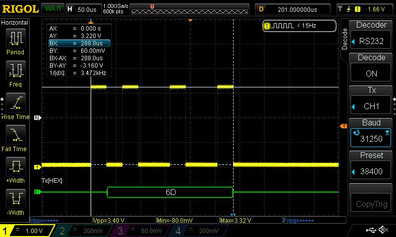
Above is pin 74 kicking out the value 0x6d that I manually wrote to register 9 via the debug command line interface in the librarian "term" mode (the command was "9 0x6d wr ").  The baud rate is 1MHz/32 = 31.25kHz; the data is LSb first, one start bit and one stop bit.  You can't see the stop bit here because it has the same low level as the following quiescent line non-activity, but we can measure the 9 bits and see that indeed 9/288us = 31.25kHz.

I know it was a long time ago, but why oh why did they pick such a slow and non-standard BAUD rate for MIDI?  Why not 38400 at least?  I mean, what were they thinking?  They had a 1MHz processor and just wanted to kick out a byte every 32 cycles?  Not that it matters to me all that much as it's just build parameters, but still, one bad engineering decision can cause untold mayhem for thousands of poor EEs for decades to come.

There are no current plans to do MIDI RX IN on the D-Lev, that would be a fairly huge undertaking requiring more cycles and memory that aren't available, not to mention an architectural overhaul that I'm not very interested in.

Anyway, I'm semi-stoked over this MIDI project!  Need something to keep me off the streets...

Posted: 3/11/2021 7:46:56 PM
dewster

From: Northern NJ, USA

Joined: 2/17/2012

The above waveform is inverted!  Took me half the day to figure out that the quiescent line level is high - I kept getting channel 1 pitchbend messages after only entering two bytes, consistent yet confusing.  Finally just dragged the scope up to our RD700NX to see what's what.  The midisnoop program is your friend!  Upward and onward...

[EDIT] Read a nice series of blog posts re. DIY breath controller this morning:

http://gordophone.blogspot.com/2013/01/a-series-basics-of-diy-wind-controllers.html

It seems the pitch side is much more straightforward than the volume side when it comes to non-percussive controller MIDI coding.

Posted: 3/12/2021 2:40:09 PM
dewster

From: Northern NJ, USA

Joined: 2/17/2012

"I do it to avoid the trappings of wealth and fame." - Andy Zaltzman

Posted: 3/12/2021 3:48:21 PM
pitts8rh

From: Minnesota USA

Joined: 11/27/2015

"There are no current plans to do MIDI RX IN on the D-Lev" - Dewster

I never grasped what MIDI IN could be used for other than possibly some control or preset/librarian communications.  But a Peter Pringle post on LevNet pointed out that while the Ethervox could not surprisingly be used as a midi controller for recording to a sequencer using MIDI OUT, it could also be used as the synthesizer to play back from the sequencer using MIDI IN.

Now this second part always struck me as sort of a "why would you want to do that" sort of thing.  After all, what sound generator within a theremin can compete with even the most basic standalone midi synth out there?  But then I realized that you could record your piece to the sequencer, and play it back identically (I'm not sure that this is entirely true) and treat the recording as just another midi instrument track rather than dealing with an audio track. 

But the best part might be that you could have full midi editing tools at your disposal to fix your theremin playing sins.  If you need to fix a sharp or flat note you could simply process that particular midi controller instead of resorting to some pitch correction software that works on audio or attempting to punch in a correction.  The same goes with volume. And tempo and timing could be adjusted slightly to track other midi accompaniment.

This is probably pretty widely known by anyone close to the Ethervox, but I thought it was interesting.  Not to worry though, just having MIDI OUT on the D-Lev to drive external synths would be a pretty big deal .

Posted: 3/12/2021 5:52:07 PM
dewster

From: Northern NJ, USA

Joined: 2/17/2012

"But the best part might be that you could have full midi editing tools at your disposal to fix your theremin playing sins.  If you need to fix a sharp or flat note you could simply process that particular midi controller instead of resorting to some pitch correction software that works on audio or attempting to punch in a correction.  The same goes with volume. And tempo and timing could be adjusted slightly to track other midi accompaniment."  - pitts8rh

The best of all worlds from a Theremin MIDI standpoint might be to just have MIDI OUT and write a plugin to emulate the modest D-Lev synth.  Then you wouldn't have to leave the PC editing & recording environment to render the MIDI to digital audio, and you could articulate the controls, apply convolutional reverb, etc. 

Most hardware synths are synths first and controllers second.  When the controller is a keyboard it makes a lot of sense to have them internally connected via something like MIDI, then just pipe the controller to MIDI OUT, and merge the MIDI IN to the synth.  On a Theremin, MIDI OUT and IN are two very different cans of worms.

The D-Lev is a controller first and a synth sorta second, with no access to the interface between them.  The interface isn't percussive or event driven and is relatively high bandwidth (axis bandwidth isn't super high but the update rate is 48kHz) with 32 bit resolution.  This makes MIDI a particularly bad fit (some would say a performance data meat grinder) hence my foot dragging until the very end here to even entertain adding it.  I think everyone wins when the synth is specifically tailored to the controller and they are tightly integrated.

But MIDI will probably be a fun thing to mess around with!  The D-Lev played it's first MIDI note today: I poked a few byte writes to the processor register set and the free synth Yoshimi responded with a string pad sound.  Yay!  Even the longest of technical journeys begin with these sorts of baby steps...

You must be logged in to post a reply. Please log in or register for a new account.