Let's Design and Build a (mostly) Digital Theremin!

Posted: 12/20/2012 1:04:17 PM
snazzy_snail

From: Minsk, Belarus

Joined: 6/21/2012

Hi. I also would like to contribute some how to a "(mostly) digital theremin project".

I'm planning to implement a digital theremin as my student's project soon, so I started making some sketches.


To detect changes in antennas capacitance I plan to use Analog Devices AD7150 Capacitance-to-Digital Converters (CDC). This converter can detect up to as minimum as 4pF capacitance with the resolution of 1 fF at a 100 Hz rate. The data from CDC is read by FPGA via I2C interface.

A sine wave can be generated in FPGA in digital form with the use of Direct Digital Synthesis (DDS) ipcore and then sent to Digital-to-Analog Converter. At the same time DDS's frequency can be altered according to the capacitance value read by pitch-channel CDC.

As for volume control, we can simply multiply a digital sine amplitude by a scaling coefficient before sending it to DAC. The coefficient is determined by the volume-channel CDC data.

If this is going to work, we should get an analog sine at the output of DAC, which can later be amplified or adapted in any way to be sent to he speaker.

Please, let me know what do you think of my plan. Does it look as a working idea or do I miss something obvious?


Posted: 12/20/2012 5:29:13 PM
dewster

From: Northern NJ, USA

Joined: 2/17/2012

"Please, let me know what do you think of my plan. Does it look as a working idea or do I miss something obvious?"  - snazzy_snail

I spent maybe 15 minutes looking at the datasheet.  The main things that jump out at me:

1. The CDC has 12 bits of resolution.  The average has 16 bits.  12 bits really aren't enough for pitch, 16 is close.  And that's if all the bits are stable or the lsbs are dithering in a way that you can use them.  If you set the settling time constant to get good (stable & enough bits) data it will likely make the response time too slow for vibrato and the like.

2. The excitation voltage (+/-VDD/2) is probably too small for reliable long range capacitive sensing. 

These chips are made more for close proximity detection, and while very intriguing I don't believe they can be adapted easily (or at all?) for serious digital Theremin use.

If you do go this route, is there any reason you're using an FPGA?  Just about any processor should be able to handle the I2C interface and audio generation, and doing more complex data manipulations with a processor would be more straightforward as well. If you really want to use an FPGA you could use it to stimulate an LC tank, or at least as an averaging frequency (period, actually) counter driven by a conventional LC oscillator Theremin front end.

Posted: 12/20/2012 7:54:34 PM
snazzy_snail

From: Minsk, Belarus

Joined: 6/21/2012

1. The CDC has 12 bits of resolution.  The average has 16 bits.  12 bits really aren't enough for pitch, 16 is close. 

How is it possible to define what will be enough?

If you do go this route, is there any reason you're using an FPGA?

Simply because I have one available (:

If you really want to use an FPGA you could use it to stimulate an LC tank.

Not sure, if I understand you. What I thought would do is using it as a controlled audible frequency generator.

Posted: 12/21/2012 2:15:57 AM
dewster

From: Northern NJ, USA

Joined: 2/17/2012

"How is it possible to define what will be enough?"

Even though you are using a sensor that measures capacitance linearly, Theremin antenna and hand capacitance is roughly given by:

Chand = pi*epsilon0*L / (10*ln(4*x/D))

where:
L = length of antenna in meters
D = diameter of antenna in meters
x = distance from hand to antenna in meters
epsilon0 = permittivity of free space = 8.85E-12 Fm^-1

So you have a 1/ln(x) relationship of capacitance to hand location.  What you want is a number that increases exponentially (the ear response is logarithmic in both pitch and volume, so it perceives exponential pitch changes as linear) with linearly decreasing hand distance.  To sort of linearize what you will actually get from your proposed arrangement, you could subtract a fixed number very close in value to it.  This is what all analog Theremins do via heterodyning.  Adjusting this fixed number for a somewhat linear middle zone will give cramped notes near and far from the antenna.

Mapping non-linear functions to discrete binary levels often gives you too much resolution on one end and not enough on the other.  For instance, you want frequency steps in the midrange to be maybe around one cent so that you don't hear the steps happening.  Expressed as a ratio this is the 1200th root of 2, or ~1.00058.  Subtracting 1 gives 0.00058 or 1/1730, which is around 2^11.  So for the center octaves you need maybe 10 bits per octave minimum, and depending on the mapping of bits to actual frequencies this either gets progressively better or worse for the other octaves.  If it gets worse for the lower octaves that would be a good thing as our sense of pitch isn't so good down there.

"Not sure, if I understand you. What I thought would do is using it as a controlled audible frequency generator."

My recommendation would be to use an inductor somehow so you get a higher voltage swing at the antenna, to this end you could use the FPGA in a feedback arrangement to stimulate a resonant LC circuit into oscillation (what I'm doing in this project).  Otherwise you could employ a conventional discrete LC oscillator and use the FPGA to precisely measure the period of the oscillations via averaging (this is likely the easiest solution for you).

Here's a unitless qualitative analysis of the kind of pitch linearity one might achieve with a linear C sensor like the IC you're looking at:

You can save yourself a lot of time and effort by doing a bit of math and spreadsheeting before you start down a certain Theremin design path.

Posted: 12/23/2012 8:12:54 PM
dewster

From: Northern NJ, USA

Joined: 2/17/2012

There's an updated Theremin Simulation spreadsheet up:

http://www.mediafire.com/?bgzc363ctdcx8rk

- Revision History -
2012-1-22 : v5
> Added Cin and tank_mode=2 to "Frequency Response" and "Full Sim" worksheets.
> Major cleanup of "Frequency Response" and "Full Sim" worksheets, VB now runs faster.

I wanted to investigate a purely CMOS oscillator (e.g. no FPGA DPLL) like that used by Andrey Smirnov in his D-sensor:

The 6.2k resistor and 470 pF capacitor RC network gives 90 degrees of phase lag, the LC tank gives another 90 degrees, and the odd number of inverters string gives 180 degrees, so it should oscillate.  The RC network is a low pass filter, which could help suppress the upper resonance point (there are 2 in tank_mode=0 and you want to use the lower one) and the RC time constant is fairly uncritical, so it might be a handy point at which to do temperature compensation.  Interestingly, Andrey couples the EQ coil and tank coil - I'm not quite sure what the effect of that would be, but it isn't necessary for oscillation.

So there is a new component Cin and tank_mode=2 in the simulation, which is the same as tank_mode=0 but the resonance phase is evaluated at 180 degrees rather than quadrature:

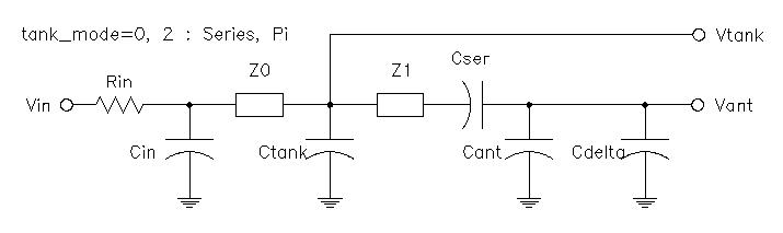
Cin, Z0, and Ctank form a Pi network.  To make this oscillate, Vtank is inverted and used to drive Vin.  Andrey uses identical values for Cin and Ctank.  I use a larger value for Cin and a very small value for Ctank, which gives more voltage swing across Ctank (which is knocked down with a capacitive voltage divider for feedback, not shown) and therefore more voltage swing at the antenna, along with higher sensitivity.  From the limited amount of simulation I've done with tank_mode=2, setting the -3dB RC point to roughly 1/2 of the operating frequency seems to be in the ballpark.

Andrey uses a 4069N for the inverters, which I believe is standard slow CMOS.  Two potential problems with that are significant delay through the string of inverters which adds phase shift, and poor current drive.  I'm using a 74LVU04N which is quite a bit faster and has much better current drive.

[EDIT] Thinking more about Andrey's circuit, he uses roughly a 10:1 turns ratio on the transformer.  This is kind of like an auto-transformer, so I believe there will be roughly 10x the tank swing at the antenna.  It's kind of ingenious.  If he can get away with not putting a ferrite slug in that coil (not sure here) there wouldn't be much drift. By using equal caps on the two sides of the drive/sense winding the I/O swing is about the same so no need to reduce the sense side with a voltage divider.

The same tank swing magnification can be done via imbalanced caps as I described above and/or imbalanced individual inductors (EQ & Tank) without coupling.  Whether the sensitivity is the same, I can't say.  Though Andrey is dividing the output down and running the resulting audio square wave to a sound card for measuring, so he must have the same needs that I do in terms of resolution and sensitivity.

Posted: 12/24/2012 1:26:18 PM
snazzy_snail

From: Minsk, Belarus

Joined: 6/21/2012

Thank You dewster, for Your complete answers. Let me bother You a little bit more...

My recommendation would be to use an inductor somehow...

Still, is it possible to build a fine theremin with no inductors?

For example, an idea from the "Physics of the Theremin" book (I believe You've heard of it) may be used. The authors of the book describe capacitance detectors built on the basis of Schmitt-trigger oscillators, frequency of witch can be varied by antenna capacitance.

Here is pitch detector's schematics:

...so you get a higher voltage swing at the antenna.

Could You please comment on this, dewster? Am I right, saying that higher voltage swing should increase sensing range and make circuit response  to changes in capacity more steady (linear)?

Posted: 12/24/2012 5:46:31 PM
dewster

From: Northern NJ, USA

Joined: 2/17/2012

"Still, is it possible to build a fine theremin with no inductors?"

I think it's possible, but probably not practical.  Inductors can be a pain to select and purchase, but the alternative is most likely a poorly functioning circuit.

"For example, an idea from the "Physics of the Theremin" book (I believe You've heard of it) may be used. The authors of the book describe capacitance detectors built on the basis of Schmitt-trigger oscillators, frequency of witch can be varied by antenna capacitance."

I did a Google search for the book but came up empty.  Could you give me a link to it?

That circuit uses RC oscillators, something I haven't experimented with much, but FredM has extensively (I believe with uniformly poor results).  RC has the potential to give you a more sensitive circuit because the frequency is directly dependent on the inverse capacitance, whereas in an LC oscillator is dependent on the inverse square root of the capacitance.  But generating higher voltages at the antenna might be problematic, and the hysteresis threshold voltages of CMOS Schmitt trigger devices might change with temperature / voltage (?) which could give you drift problems.  I believe FredM was using a 555, I think I'd try a CMOS 555 to reduce capacitive loading if I were going this route.

"Am I right, saying that higher voltage swing should increase sensing range and make circuit response  to changes in capacity more steady (linear)?"

Higher voltage swing at the antenna tends to swamp out environmental interference (60Hz hum, radio, compact fluorescents, etc.).  To this end it increases SNR and gives you a better instrument.  If there is any digital switching going on in your Theremin a higher voltage swing can make the pitch section more immune to that as well.  An EQ coil in series with the antenna can extend the playable range and make it more linear seeming.  It can also boost the voltage.  But other than that I don't believe antenna voltage swing and perceived linearity are related phenomena.  I'd recommend somewhere between 50V and 150V at the antenna, but I haven't actually studied this in any depth.

I must say, your request for information here is pretty much what we hope to address at some point in the future with the TW Theremin project.  We'd be able to point you to the schematic of a proven oscillator that you could just bolt on to a digital section.  Until then, you might look at the Moog Ether Wave schematic, the two transistor oscillator in that is fairly robust, but it requires a higher voltage dual supply.  Or you could use my tank mode 2 above, with 50mH inductors for Z0 and Z1 (Bournes 6310) and complete the feedback with 74LVU04N inverters (single 3.3V supply) - if you're interested in going this route let me know and I can help you pick values.  Do you have a solderless breadboard and access to test equipment?

Posted: 12/24/2012 7:52:24 PM
snazzy_snail

From: Minsk, Belarus

Joined: 6/21/2012

I did a Google search for the book but came up empty.  Could you give me a link to it?

Sure! Seems to me that You have it on Your mediafire. The file is called "Theremin_Am_J_Phys_excellent.pdf". Otherwise, You can take it here.

Also, I have found a notice about this theremin on the Art's Theremin page.

*"Physics of the Theremin" is actually an article, not a book. My mistake.

Posted: 12/24/2012 8:00:47 PM
dewster

From: Northern NJ, USA

Joined: 2/17/2012

Oh, OK, thanks!

Uh oh, this is the infamous Glasgow Theremin.  Lots of people here have lots of bad things to say about it.

Posted: 12/24/2012 8:19:16 PM
snazzy_snail

From: Minsk, Belarus

Joined: 6/21/2012

Oh... What are those "bad things"? Maybe You could point me to (a link or smth, not to flood the topic)? 

You must be logged in to post a reply. Please log in or register for a new account.