Theremin Circuits Scratchpad

Posted: 1/14/2013 3:42:17 AM
dewster

From: Northern NJ, USA

Joined: 2/17/2012

"This is one of the big problems with electronic parts - the economies of scale are HUGE .. In some cases one can buy ten items for twice the price that one item costs, once one factors in postage etc."  - FredM

Where I used to work we'd get all kinds of stuff, including high-end FPGAs, for dirt cheap compared to the one-off street price to the average Joe.  The power of a big corp dealing with another big corp I suppose - and who golfs with whom.

Posted: 4/21/2013 2:41:19 PM
Juan

From: Valencia, Spain

Joined: 4/21/2013

Hello to the experts. This is my first post to ThereminWorld, althoug I have been playing with theremin circuits for  long time. I have learned a lot from Fred, Thierry, Dewster, etc.

Just going back to the first question of Fred, I think that it is quite clear that original Thermen ocillators (in RCA, and in Clara Rockmore schematic by R. Moog) are not Armstrong oscillator. But they are not so strange oscillators, they are really of Hartley type. More specifically they are shunt-fed magnetic-coupled Hartley oscillators 

This is quite evident if you examine the small AC signal circuits.  In original Thermen oscillator, always one end of each coil is at AC ground (the coil to triode screen is at DC ground, and the coil from anode is at VCC, this is AC ground too). Then the "hot" end of both coild are  joined by C. Rhis is a "typical" Hartley tank, but usually in the shunt-fed Hartley, the AC ground are both real DC ground or both VCC. The peculiar characteristic in Thermen oscillator is that one coil is at AC ground in DC ground , and the other is at AC ground in VCC.

I have done some simulations and redrawings of Thermen oscillator to show this fact. I am trying to insert images with the schematics and simulations results but without success.

The equivalent "L" in a magnetic coupled Hartley Oscillator is L=L1+L2+2M, being M the magnetic coupling, in the ideal situation (with perfect coupling k=1) M=(L1*L2)^0.5. Therefore if L1=L2=165uH, as in the RCA coils, the L=165+165+2*165=660uH. So the resonance frequency is of C=1100pF with this equivalent L, that is around 185KHz.

I think that Fred was wondering if L1 should be equal to L2. This is not a condition for a Hartley oscillator. Usually L1 is lower than L2 (being L1 the coild to the tube anode, and L2 the coil to the control screen). Thermen oscillator feedback being L1=L2 is very high,and in the original configuration control screen positive voltage excursions are terrible for the tube health. The original tube in RCA was a "big bottle" triode, probably quite able to stand big currents in control screen (positive screen voltage in respect to cathode). This is not possible with most of the currently available triodes (such as 12AU7, that probably is good election for a RF oscillator). I think that in any case, original Thermen oscillator was stressing the tube a lot (triode screen currents are not welcomed in any case), and reliability was probably not very hight (but i dont really know).


Posted: 4/21/2013 3:44:37 PM
Juan

From: Valencia, Spain

Joined: 4/21/2013

I am attaching a series of circuit simulations:

I have used 12AU7 triode for the simulation (I found a model om the web taht seems OK(. 12AU7 is a current production triode that is indicated for RF oscillator (low mu, high g).

I have simulated five circuits. Thermen-A is a direct adaptation for 12AU7 of original RCA/Rockmore theremin. It stresses the tube directly into destruction (even that the oscillation signal is nice). Thermen-B decouples the control screen form the tank, and is a much better for the tube. In a triode tube the dc voltage of screen should be some volts negative in respect the cathode. Lev used a little strange biasing method (it works, but at least in the strating, an excess of current is going through the tube). The circuit named Thermen-C uses a more normal biasing scheme (equivalent to the used in a JFET).

Then I have added Hartley oscillators. Hartley-A is a shunt-fed magnetic coupled oscillator, more or less normal in the litearture. Hartley-B is the same Hartley, but instead of having coild grounded thay are to VCC. This Hartley oscillator is illustrated and discussed in RCA Radiotron ed4 page 951 (please note that for tube enthusiasts, citations to RCA Radiotron are mandatory, this is considered the Bible. I own an original of 1953, but searching in the web it is easy to find pdfs of several sections of the book, including the oscillator chapter).

My conclusion is that Thermen-C and Hartley-B are exactly the same circuit. If terminal 1 of L5 is grounded instead of VCC, then we have the Thermen oscillator. In fact, as L5 is isolated by capacitors, this point is AC ground in any case. So, Thermen oscillator is a variety of Hartley. But I have never seen this fact in any book, so at least it is a new  Hartley variety.

Next I'll try to show the simulations results.


Posted: 4/21/2013 3:48:34 PM
Juan

From: Valencia, Spain

Joined: 4/21/2013

Oops, the drawing seems to be cut.

Posted: 4/21/2013 4:39:57 PM
Chobbs

From: Brooklyn,NY

Joined: 12/1/2009

Interesting- great work... It may be helpful to take a look at the keppinger theremin which uses hartley oscillators and 6SN7's.   The 'new'  version , model K  even uses 6C4's, which I believe are 1/2 a 12AU7. 


  I lack the engineering chops to really chime in, but just keep in mind the oscillator coils that Lev used in the RCA and all his other theremins (afaik) are double-wound - two layers on the same form; more akin to the tickler in an Armstrong configuration.   (Again I dont have a lot of experience here, but ...)  Harleys generally are a single coil with a tap somewhere in the middle.   it is  far easier to wind a single tapped  coil or even two seperate coils than it is to wind the double layer one.   Ive done it many times- they are a bitch.   I have to conclude that there is a real reason that Termen stuck with this design.


Posted: 4/21/2013 4:57:55 PM
Chobbs

From: Brooklyn,NY

Joined: 12/1/2009

Interesting- great work... It may be helpful to take a look at the keppinger theremin which uses hartley oscillators and 6SN7's.   The 'new'  version , model K  even uses 6C4's, which I believe are 1/2 a 12AU7- though that one sounds like crap. 

    I lack the engineering chops to really chime in, but just keep in mind the oscillator coils that Lev used in the RCA and all his other theremins (afaik) are double-wound - two layers on the same form; more akin to the tickler in an Armstrong configuration.   (Again I dont have a lot of experience here, but ...)  Harleys generally are a single coil with a tap somewhere in the middle.   it is  far easier to wind a single tapped  coil or even two seperate coils than it is to wind the double layer one.   Ive done it many times- they are a bitch.   I have to conclude that there is a real reason that Termen stuck with this design.


Posted: 4/21/2013 4:59:34 PM
Chobbs

From: Brooklyn,NY

Joined: 12/1/2009

Interesting- great work... It may be useful to take a look at the keppinger theremin which uses hartley oscillators and 6SN7's.   The 'new'  version , model K  even uses 6C4's, which I believe are 1/2 a 12AU7- though that one sounds like crap. 

    I lack the engineering chops to really chime in, but just keep in mind the oscillator coils that Lev used in the RCA and all his other theremins (afaik) are double-wound - two layers on the same form; more akin to the tickler in an Armstrong configuration.   (Again I dont have a whole lot of experience here, but ...)  Harleys generally are a single coil with a tap somewhere in the middle.   it is  far easier to wind a single tapped  coil or even two seperate coils than it is to wind the double layer one.   Ive done it many times- they are a bitch.   I have to conclude that there is a real reason that Termen stuck with this design and that the physical proximity of one winding on top of the the other does something not obtainable with simpler coil designs.


Posted: 4/21/2013 5:47:03 PM
FredM

From: Eastleigh, Hampshire, U.K. ................................... Fred Mundell. ................................... Electronics Engineer. (Primarily Analogue) .. CV Synths 1974-1980 .. Theremin developer 2007 to present .. soon to be Developing / Trading as WaveCrafter.com . ...................................

Joined: 12/7/2007

Thank you Juan, This is  really enlightening research you have presented ! - And from first cursory look at it, I think you are right on your conclusions.

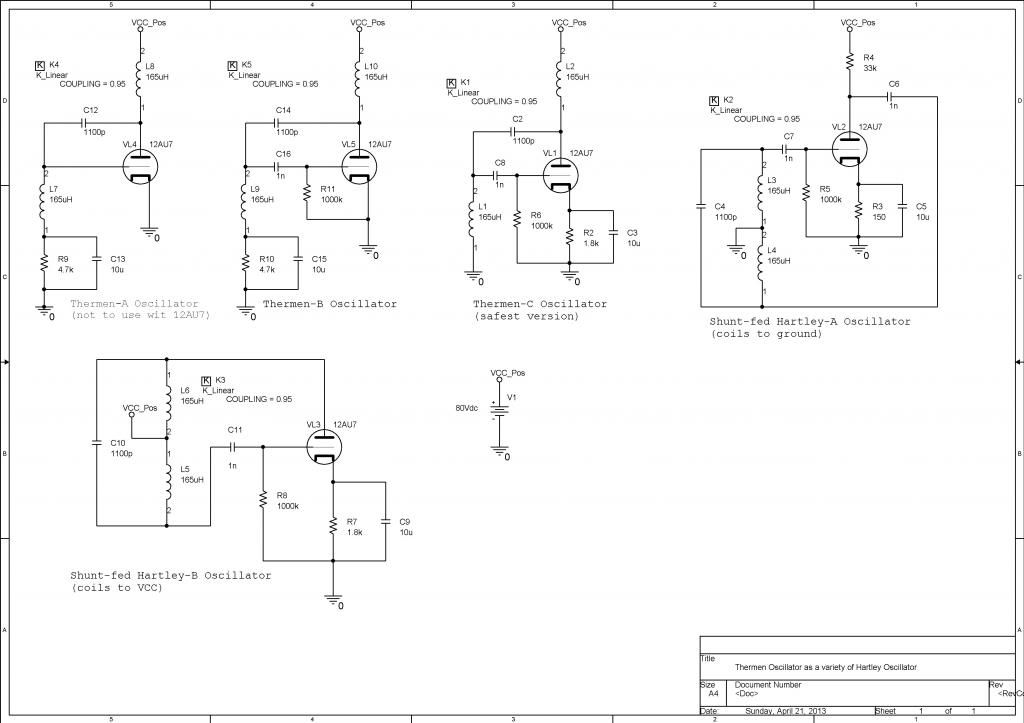
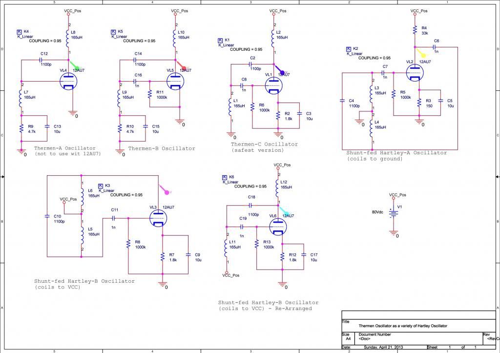
"I think that Fred was wondering if L1 should be equal to L2. This is not a condition for a Hartley oscillator. Usually L1 is lower than L2 (being L1 the coild to the tube anode, and L2 the coil to the control screen). Thermen oscillator feedback being L1=L2 is very high,and in the original configuration control screen positive voltage excursions are terrible for the tube health. The original tube in RCA was a "big bottle" triode, probably quite able to stand big currents in control screen (positive screen voltage in respect to cathode). This is not possible with most of the currently available triodes (such as 12AU7, that probably is good election for a RF oscillator). " - Juan

On my first evaluations / experiments I had L1 and L2 unequal - I only changed to equal inductances due to Charlies posting of a Levnet email from "Uncle Howie", and my wish to explore whether this configuration was beneficial in any way.. I think  this email steered the direction (or certainly my direction) away from its original course, and into exploring the Lev theremins, with the object of understanding them and replicating them using semiconductors.

I think one cannot take the oscillator (whatever topology) on its own without including the antenna circuit - and I believe it is here that the "special" qualities of the Lev oscillator ( "shunt-fed magnetic-coupled Hartley oscillators" ) may become significant - And particularly where the construction of the coupled L1/L2 windings becomes important.. I think that perhaps this construction is critical for linearity - my attempts at producing small transformers for L1/L2 have (particularly those on ferrite formers)  not given as good results as large air coils more loosely coupled.... But in all, the results are far less spectacular than I first thought.

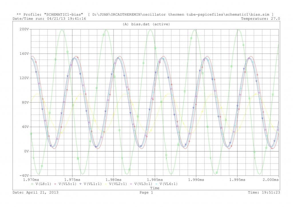
With regard to over-driving the tubes - I wonder whether this affects the waveshape / harmonic content from these oscillators? If it does, then keeping this "feature" would be important for true replication of the Lev theremin designs, regardless of how achieved.. My focus was on in-mixer waveform shaping, as I believed the mixer was the primary mechanism for the Lev theremins sonic qualities, and the antenna circuit / oscillator the way the famed linearity was achieved.

"I have to conclude that there is a real reason that Termen stuck with this design." - Chobbs

I must agree that I think you are right!  - However, with available modern components (and difficulty obtaining the parts Lev used),  I no longer think that WE have any real reasonn to stick with Lev's design.

Where I am with this:

For me, its been an exciting diversion - and I learned a lot from it - But I see nothing in the Lev designs which cannot be better implemented using modern components and different topologies.. There is a strong "romantic" pull towards duplicating Lev's theremins using the same topology he did.. But IMO this route is probably folly today.

To me, one wants to duplicate two things from the Lev theremins - You want its responsiveness (linearity / sensitivity etc) and its sound.. It doesnt matter how one gets there - if you achieve these you have a "clone" regardless of whether it uses an analogue subtractive synth engine, or an additive engine, or a sub-sampling theremin or whatever...

And even better if the "Lev clones" are just a set selectable presets amongst a selection of many more presets to include later theremin sounds and synthesisers.. A "Lev Clone Plus" if you like.. With the front-end having modern/new features like adjustable sensitivity (range) and linearity, and register switching.

IMO, the trouble with the theremin is that it has been "imbued" with "qualities" it simply does not posess - All theremins, at the end of the day, right from the first prototype on Lev's bench, output an audio waveform - there are no "mystical" or "fragile" qualities in any waveform - Everything we can hear can be seen and analysed way beyond or ability to hear.. Produce the same audio waveform as the RCA for the same physical actions, and you have a true "RCA Clone" regardless whether the audio is produced by two chickens being heterodyned or by a FPGA.

Posted: 4/21/2013 6:11:08 PM
Chobbs

From: Brooklyn,NY

Joined: 12/1/2009

"And even better if the "Lev clones" are just a set selectable presets amongst a selection of many more presets to include later theremin sounds and synthesisers."


I gotta disagree...theremins  using  synth-style wave shaping always sound like synths.  Etherwave, e-pro,  you name 'em-  most if not all currently available designs process the signal using synth topology (waveform, etc) - and relative the 'originals,'    to me, they all kinda sound like various synth patches.   personally I feel the 'pure' heterodyne tone of lev's instruments are what give them their unique and elusive tonal character.   

the kep has a 'un processed' signal and sounds warm and rich, but (probably because of the different osc type)  doesnt hold a candle to my little fet-based theremin w/ RCA coils.

Posted: 4/21/2013 6:27:06 PM
Juan

From: Valencia, Spain

Joined: 4/21/2013

I am updating the drawing (in color) and adding the output.

I the colour of the "probes" in the circuit is the colour of the plot. I have re-arranged "Hartley-B" schematic in a similar way to "Thermen-C". The only difference is the connection for the coil to the control grid (to GND in Thermen, to VCC in Hartley, but both signal AC).

In the plot: the high amplitude is Thermen-A (Green). Red, marine blue and magenta outputs are quite similar, so are the schematics. Magenta and sky-blue are identical. Yellow is Hartley A-, lower amplitude because amplifier part of oscillator is lower gain. A FFT analysis shows that the output is a very good sinus.

Chobbs, thank you for the comment. Yes, usually Hartley coils are described as tapped, but in fact the geometry does not matter. If you connect both windings in series in a normal RCA coil (provided correct winding direction), you really have a single coil tapped in the middle. You are right that coupling will be higher with a double bound coil than with a tapped single layer coil. But I think that the difference will be minimal. Mutual inductance will be very tight in both cases.

By the way, I have taken the output for the simulation from the anode (the plate) of the tube, which is the usual practice. RCA and Rockmore oscillator outputs are taken from the screen, which is quite abnormal. I think the explanation is in this way you can direct-couple the signal to the grids of the mixer tetrode, because there is a DC negative component in the oscillator signal that provides the bias to the tetrode (more or less). Coupling the signal from the plate requires an additional capacitor (RC coupling).

Also, I think that Lev Thermen schematic for RCA and C. Rockmore are influenced for the fact that in the 1920s capacitor were not so reliable, were expensive, and required maintenance (waxed paper technology, electrolites that dried, etc.). So, inductive coupling (with audio interstage transformers) was more reliable and a design with less capacitors was better. The Thermen topology (Thermen-A in my drawing) has less capacitors than the others, so it is better for the technology of the time.

I am going to convert all these topologies to JFET and I'll post it (simulation is cheap and easy).


You must be logged in to post a reply. Please log in or register for a new account.