TECHNICAL HIJACK!

Posted: 8/18/2014 10:26:54 PM
FredM

From: Eastleigh, Hampshire, U.K. ................................... Fred Mundell. ................................... Electronics Engineer. (Primarily Analogue) .. CV Synths 1974-1980 .. Theremin developer 2007 to present .. soon to be Developing / Trading as WaveCrafter.com . ...................................

Joined: 12/7/2007

Great drawings!

For linearity measurement, I am inclined to think that only linear movement will approach "real", but I could be wrong..

In fact, I am inclined to think that chasing perfect linearity or even making any kind of "standard" comparison is probably utterly futile - People play differently, have different bodies, and have different ideas about "ideal" linearity for them.. And the environment changes, the air dielectric changes with temperature and humidity, and this probably affects linearity as much as it affects pitch.

But for what its worth, this is (or was) my ideas on the subject of the geometries of Linearity .. I was trying to be scientific when I wrote that, now I think that I was just wasting my time.

I think most people probably only notice gross non-linearity, and it seems from recent revelations here that people only notice gross latency - that perhaps say 30ms latency is acceptable to most but 120ms is noticed by most.. Who knows ;-)

Fred.

Posted: 8/18/2014 11:20:03 PM
xtheremin8

From: züriCH

Joined: 3/15/2014

fred, you hit the nail on the head. it's not worth the effort, so i tried to post the picture with the remark:"can be  deleted to save space". but i listened to dewsters  mp3 sweeps and read again how he did it i unterstood what he meant, and a device that does the sweeps would shurely be helpfull. so i would probably salvage a old fan, hotglue some bicycle spike on the fanblades, and use a sewing machine power pedal for speed control. then i would probably light that cold fag in my mouth.  i'm really looking forward on the digital theremin. 

People play differently, have different bodies, and have different ideas about "ideal" linearity for them..i play a 145-harrison, a shifty beast when batteries go low, with plate-antennas, mounted on a ball joint and i guess only i can play it in such a twisted way to achieve my own linearity  and my lousy bmi does the rest. maybe i'm a bit therepathetic too! ;-)


Posted: 8/18/2014 11:28:53 PM
RoyP

From: Scotland

Joined: 9/27/2012

xtheremin8

I have a Harrison 145 also which I have converted from plate antennae to rod antennae and it works very well.
Art also supplied me with a conversion to make the volume antenna work in the usual theremin way (hand close=quiet).
I agree, it is a bit challenging when the battery is weak but (I'm working on that) I love the timbre and it has a reasonable linearity.

Posted: 8/19/2014 12:53:09 AM
FredM

From: Eastleigh, Hampshire, U.K. ................................... Fred Mundell. ................................... Electronics Engineer. (Primarily Analogue) .. CV Synths 1974-1980 .. Theremin developer 2007 to present .. soon to be Developing / Trading as WaveCrafter.com . ...................................

Joined: 12/7/2007

Re: Page 7 of this thread.

All I can do is re-post this (link was on TW before)

http://www.mb-labo.com/Theremin/t-Vox.htm

Auto translate from Japanese:

NEW!
Production report an extra edition of the theremin     Under construction! !
I look through the t-VoX
It is believed to have been purchased by the time this was borrow your t-VoX from those who are learned in the same theremin classroom, and since it is a memo with 2001-June to the nameplate on the bottom.
I saw the tone and tied with a rope was placed on a wooden board on which is fixed a plate with nut stand for the set screw does not fit in the adapter on hand size larger than Ether wave theremin.
Pitch is easy to play even the pitch of the octave between easy to adjust, volume control is set adjustment knob and press the set button with your hand to the desired height without.
It had heard the condition of the VOL is bad from the person who was borrowed, but it seems good.
Tone is feeling close to a sine wave or will say that it sounds sober Toka straightforward than Ether wave theremin.
We have heard such information may be unstable noise from entering or in the installation environment, but in my place, it becomes the sound is cloudy in places As you change the pitch, to feel 60Hz components, such as mixed It will not be improved by connecting a ground wire trout, the bottom plate, good measures is not so far been found.
Was let me take the photos Remove the cover gently so that borrowed it and of good and look inside.
 

I might change the title of a later date (provisional data and waveform of 0) t-VoX!)
Measured picked up from the antenna to hit the probe directly to the circuit just quit semiconductor that appeared purchased separately can not be measured in most domestic and frequency waveform is because it is being used.
Waveform: was expected from the sound quality heard but much lower frequency up was nearly sinusoidal.  
 
Was a very modest seasoning to the extent that the waveform is distorted slightly by turning full (SHAPE) sound quality adjustment knob.
Frequency · PITCH: about 130Khz
Frequency · VOLUM: 330Khz

Appearance of 1) t-VoX  
Sites that are out of the photo will be found soon as a search for "t-VoX" appearance, but I was also UP.


Oscillation unit 3) t-VoX (main board)
Oscillation seems to be a dual-gate FET CAN type of four-legged only one stone, looking at the pattern of the chip resistor and capacitor of the peripheral.
Can not otherwise be discovered by searching in http://www.alldatasheet.com/ such a symbol that appeared FET and type name, kana FET made ​​in Russia? .
Oscillation circuit is a simple circuit consisting of a tuning coil FET1 and stone, the reference side is a circuit similar to the pitch side except for the variable capacity condenser.
Coil is like a turns ratio Na is much larger than the oscillation for AM radio in variable inductance type went into the metal case.
There is no antenna coil, but the pitch of the octave between easy to play and have become equal.

VOL control circuit is in a separate board, but the VCA IC is disposed on the main board.
Observation of the waveform and voltage to Oazuke semiconductor that is being used because it is very Breaking in most IC does not seem to stock in the shop can buy the parts of the electronic work Excluding logic IC! .
A mail order can shop could not find the logic IC other than data sheet was available

VOL control circuit of 4) t-VoX

I suspect LMC555 in this oscillation IC for about 10 months is riding on the substrate of the VOL control.
It is set span adjustment circuit of the volume control is composed of VCA, digital potentiometer, a logic IC or the like, you can press the button with your hand to the desired height.
On / off switch circuit of the audio-out, Myuteingu circuits are arranged on the substrate.

Oita greater than Ether wave theremin (500w 220d 49h) is light on the other size.

Screw-in, may just plug joint portion is has become a slotted antenna is VOL, pitch antenna Both AL pipe made ​​of 12Φ

Outer casing bottom of the plastic steel plate

The UP was so can not be found even looking at the web photos of the inside of the internal <BR> 2) t-VoX.
Simple, coils 3 pcs. Only much, accessories circuit looks to the circuit was pretty weird contrast than Ether wave theremin oscillation circuit.
You ... I want to also analysis of the circuit from the photo at a later date.

From other sites: (http://www.atelier-theremin.info/Frameset/Instruments-Frame_Frameset.html)

Fred.

Posted: 8/19/2014 1:53:46 AM
dewster

From: Northern NJ, USA

Joined: 2/17/2012

"We have a saying here in the States, that some people become so smart they get stupid."  - Touchless

A scientist knows more and more about less and less till he knows everything about nothing, while a philosopher knows less and less about more and more till he knows nothing about everything.  -Unknown

Now I hope that is not going on here because I want dewster to win. I just can't place my bet on him anymore.

I coulda been a contender!

Posted: 8/19/2014 2:17:46 AM
xtheremin8

From: züriCH

Joined: 3/15/2014

roy: i saw your lovely 145 on arts page. and  your cool videos! my theremin is also on arts site, somewhat above yours. {but i haven't got the guts for vimeo,yet .}  i also love the sound but never reversed the volume. i did that on the ew+ instead! btw: there should be a why do u love art harrison theremins topic. ;-)

dani


Posted: 8/19/2014 2:37:33 AM
Touchless

From: Tucson, AZ USA

Joined: 2/26/2011

I have seen a softer gentler side of dewster and fred this week, maybe they could have been somebody.

Posted: 8/20/2014 12:52:01 PM
FredM

From: Eastleigh, Hampshire, U.K. ................................... Fred Mundell. ................................... Electronics Engineer. (Primarily Analogue) .. CV Synths 1974-1980 .. Theremin developer 2007 to present .. soon to be Developing / Trading as WaveCrafter.com . ...................................

Joined: 12/7/2007

This is from hijack started on musical saw thread:

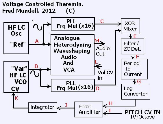
* x16 multiplier is, IMO, the minimum - The bigger the multiplier, the lower any latency, but the higher the multiplied difference frequency (F) and PLL output frequencies (C+D), C+D will depend on HF oscillator frequencies, and these need not be high (say 150kHz minimum).. I used 74HC4046 PLL's with about 12MHz top frequency, but they seem to behave better below about 10MHz, so I ran at ~200kHz with x32 multipliers giving ~ 6.4MHz which works even with the slower 4046 PLL.

The other thing that one needs to keep in mind is the difference frequency, with a x32 multiplier, for an audio difference span of 16Hz to 6kHz one gets 512Hz to 192kHz, and if the (multiplied) difference goes much above 200kHz it starts to become difficult to do the period to current conversion without getting into expensive components.

It should be noted that the A and B signals could be taken from any EW or other theremin oscillators, and fed to PLL's in above manner - the signal from H would then be a 1V/Octave output (one obviously would not need the error amplifier etc, as there would be no CV input... One could, of course, add these and adapt any existing theremin to voltage control if you wanted ;-) which would track right down to 16Hz with low latency (4ms - or 8ms using the EW+ converter which requires two cycles)) - Present CV output from the EW for example cannot track at all below 100Hz and has 5ms latency time even up at 400Hz (10ms @ 200Hz, 20ms @ 100Hz) , wheras the above scheme reduces latency to 1/16th (or 1/ whatever multiplier us used in the PLL's) of whatever period one would measure from the theremins audio.

My plan was to use the above VC Theremin with an independent theremin front-end, this front-end would give a linear voltage output (as in, real linear - not 'scaled' to exponential for music) and one could then attenuate it to whatever one wanted to control the 'span' (how many octaves in the playing field) one wanted, and could add voltages to shift the pitch or whatever, and have multiple voices tracking each other - voices being either other CV theremin modules, or conventional 1V/Octave synths etc.

Personally, I think the 1.2V/Octave standard (Buchla) is better, it gives a tidy 100mV/semitone 1mV/cent and I would include a link option for this. (in fact I used 1.2V/octave when playing with the prototype, just because it was easier to calculate what was going on)

Also, on my prototype I didn't use an XOR or filter or ZC detector, I used a D-Latch.. Dewster showed me that there is a problem with doing this, and that accuracy is impaired - And although I never noticed this problem, he is right! - If I return to the design, I will change to the above .. I did have some problems which may well have been  D-Latch related.

The thing is though... The whole complex expensive circuit is really just a VCO (and VCA, but that's irrelevant!) .. Is it really worth the effort to get heterodyning? - I said yes, because I was looking to implement wave-shaping that could only be done at the mixer, and later  my additive synthesis engine using this method - and its a damn good way to do that.. But would someone pay say >£200 for a heterodyning VCO?

Fred.

* or 8ms using the EW+ converter which requires two cycles - Please understand that the EW+ converter would not work with such high frequencies, a better converter is needed - I used a dual slope linear integrator, effectively two integrators, so that I could complete each conversion in a  single HF cycle

>> Thinking about this.. Might have got the sums wrong! ** I would probably use a digital integrator if I was to build these, could easily get 17 bit resolution, and probably do the log conversion digitally, and get 1cent accuracy over the whole span.. Been looking at the £3 PSoC 4 board as the whole signal path from C to K could likely be done with one of these, making it a possibly realistic venture.. MIGHT even be able to squeeze the PLL's in, or at least the dividers and phase comparators, perhaps with a couple of transistor VCO's off chip.

Posted: 8/20/2014 3:34:20 PM
xtheremin8

From: züriCH

Joined: 3/15/2014

hi fred, 

Personally, I think the 1.2V/Octave standard (Buchla) is better, it gives a tidy 100mV/semitone 1mV/cent and I would include a link option for this. (in fact I used 1.2V/octave when playing with the prototype, just because it was easier to calculate what was going on)

maybe that explains the  isssues on moog-synths tracking 1v/oct. the forum there is full of that mostly minitaur/slimphatty, so the more synth-for-masses section. 

wow, your schematic goes far beyond what i imagined.  little do i know. actually my troubles began when i stupidly first time hooked up the ew+  cv's to a minitaur and expected to play poly-voiced. what a dsiapointment of course, know i now a bit more why. cv-to - vca control of a ew+ is ok. but the -2.5 to + 4.5 of the pitch side gave me a bit headache. but i think i found a solution for that.

imho: since the original theremin sound depends on the instruments physics, (RCAetc.),it comes up that every other approach to get that sound  is  imitation, so it can be produced right away by a synthesizer, formant filters etc.  and since everything goes digital and nanosized, it doesn't matter anymore how the ears get fooled.

maybe moog could have made a deeper impact with a ipad-holder with antennas on it. 

shit i'm late bye


Posted: 8/20/2014 5:13:17 PM
FredM

From: Eastleigh, Hampshire, U.K. ................................... Fred Mundell. ................................... Electronics Engineer. (Primarily Analogue) .. CV Synths 1974-1980 .. Theremin developer 2007 to present .. soon to be Developing / Trading as WaveCrafter.com . ...................................

Joined: 12/7/2007

"maybe that explains the  isssues on moog-synths tracking 1v/oct. the forum there is full of that mostly minitaur/slimphatty, so the more synth-for-masses section. " - Xtheremin

Maybe ;-) If the theremini is anything to go by though, I wonder if anyone at Moog understands V/Octave! ;-)

1V/Octave is fine - its easy to work with if you are doing octaves! ;-) ... In fact every V/Octave ratio is "fine" - as long as its always maintained at that ratio for every instrument tracking it..and the master controller NEVER changes this ratio, NEVER - not under any conditions!  If the master puts out a consistent ratio, be this 1.2V/Octave or 1V/octave or 0.5V/Octave, then a fixed gain or attenuation stage (simple opamp and/or potential divider) can adapt the CV to any other ratio (as in, 1.2V/Octave can, for example, easily be dropped to 1V/Octave)  - but if the master ratio changes, CV becomes useless, because anything tracking it wont track musically anymore!! - And the company whose founder invented  this scheme, it seems, dont even understand this!!!

The bigger the V/Octave, the better in terms of accuracy, but running 5V/Octave for example one would need a 40V span for 8 octaves.. My first synth I built when about 11years old  ran on 0.5V/octave so I could build it with 9V supply or battery - it could take a 1V/Octave input divided down to 0.5V/Octave with two resistors... But I never had (and couldn't afford) a synth keyboard so put contacts on an old upright piano keys and output 0.5V/Octave.

Its only when one is pedantically trying to check pitch against voltage that 1.2V/Octave really becomes useful, because one can put a tuner display on the audio and check that every 100mV changes the pitch by a semitone, and see exactly what any error is by changing the CV and seeing how many mV (cents) error there is between sequential semitones... The log / exponential converter is the area that has always been the biggest pain with regard to accurate tracking.

Fred.

You must be logged in to post a reply. Please log in or register for a new account.