Caglayan Tiny Theremin Build - pitch antenna issue

Posted: 8/27/2015 10:54:24 PM
xoadc

From: Moncton, New Brunswick, Canada

Joined: 4/24/2015

I just finished the Caglayan Tiny Theremin, and am about to embark on building a Thierrymin next...

but first, I'd like to trouble shoot the Tiny Theremin to get it working better, and I would love any thoughts or advice you folks would be kind enough to offer!

It currently makes sound... huzzah! (I doubted my ability and was afraid it wouldn't make any sound)  but the pitch antenna does not seem to offer any control at all.  I succeeded in making a lovely little device that makes one long note.  I can change the pitch by turning the screw in the variable capacitor... but I cannot change the pitch using the antenna.  Any ideas on what needs attention?

Once I get the antenna working on this little guy, I'll move onto building the Thierrymin, then to the PAiA and then to the Etherwave.  But first this.  One thing at a time.

Here is the schematic :

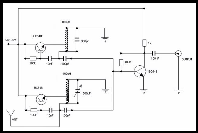
To start out, I was in search of the most pared down simple schematics out there, so that I could  better understand the fundemental principles before moving on to more complexity.


Here is the video by Chris Caglayan where I found the schematic. 
This is a little demonstration that he does with his build:

Here are the homemade coils (100 winds of 29 gauge magnet wire around film cannisters, tapped at the 20th turn).

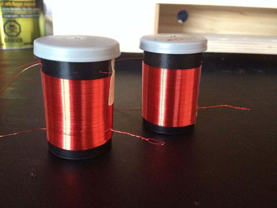
I later dipped them in varnish and removed the masking tape, and dipped a 2nd time in the varnish.


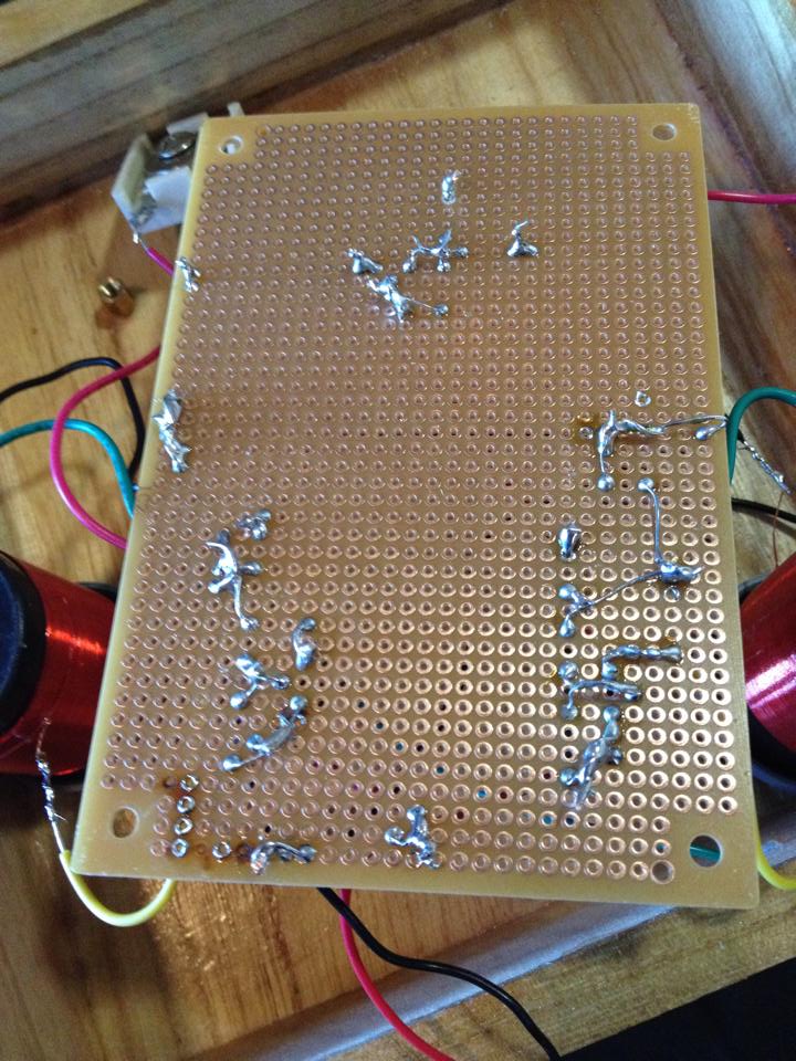
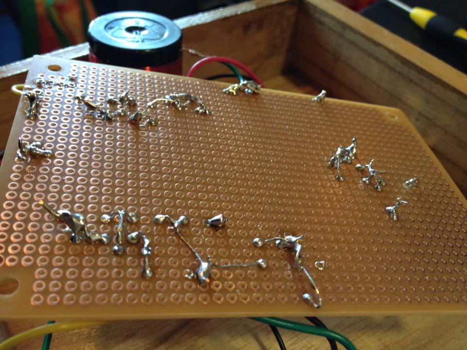
Here is my finished circuit, built on perf board, not strip board:


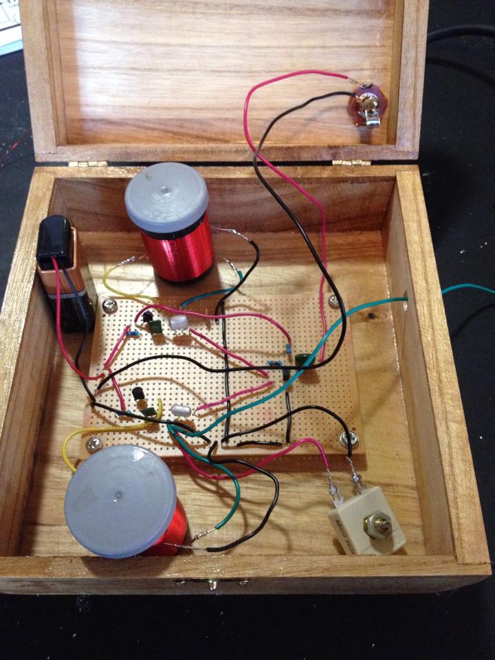
Here is a wider view:

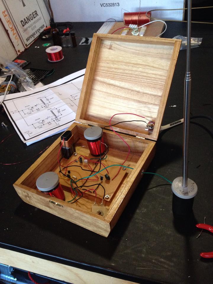
(the antenna is on the outside, because it wouldn't fit inside the box, and I want to be able to open and close the box... I'm still working on a better solution)

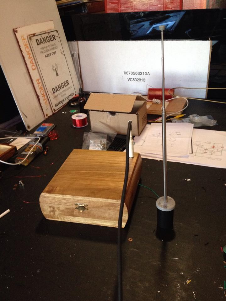
Here it is all closed up and plugged in:


Any ideas on where I should start looking and tweaking to get actual response from the antenna?

Any suggestions and advice is very much appreciated!

Posted: 8/28/2015 12:47:54 AM
oldtemecula

From: 60 Miles North of San Diego, CA

Joined: 10/1/2014

Hey Xoadc,

Good to see you again, I think you should proceed with building Thierry’s design. The first clue of a bad design is someone will use a lot of reverb and effects to cover up the design shortcomings. Notice how the original designer in the model you built never gets more than a few inches from the antenna.  These are two clues of primitive design and yet a wonderful learning experience, exploring these aspects are what teach us in the long run. I would rather have my theremin build fail at startup so I might learn something.

PS: Your coils are very nice (pretty). A theremin must be wired with very short connections, this is the first thing to correct, all those long wires at RF frequencies will create all kinds of crazy behavior, but I do like your box!

Christopher

Posted: 8/28/2015 1:54:49 AM
senior_falcon

Joined: 10/23/2014

Hi Xoacd:

Nice job building the Caglayan.  Don't give up on it just yet - I suspect it is just some simple thing that keeps it from working.  Check your wiring one more time just to be sure.  Check that the antenna is actually connected.  Your film cannisters (what the heck is a film cannister anyway???) seem to have a lot more wire than the one in the video.  I think grounding may be important - you can do a search for Etherwave grounding for more info on this. 

Posted: 8/28/2015 2:58:13 PM
xoadc

From: Moncton, New Brunswick, Canada

Joined: 4/24/2015

Thanks guys!

(yes I was gone for a while, focusing on my cabinets... tested light fastness and stuff for various materials to finish my Etherwave case... waited over time to see how colours shifted... but that's all done now and the cabinet is finished... so I can't use the case as an excuse to procrastinate on the circuits anymore... I'll post pictures of the carved and finished Etherwave case, only once the electronics are assembled)

So Christopher, yes this was a good learning experience!  It was my first time working with perf board, so I figured it was best to practice on this smaller circuit before embarking on the Thierrymin... to beef up my soldreing and desoldering skills.

Given that Caglayan was using an effect pedal in the video, I was not expecting to make a "nice" sounding instrument... I just wanted to understand the bare basics of how this works... and I think I got that!  But it doesn't really "work" yet... and I would like to get there... I think if I can figure out what's wrong... and how to make it "work"... that will be another fine step in the learning and understanding process of the basics... what makes the antenna "work"


Big learning from this so far:

understanding the FPO and the VPO - check
getting more comfortable with soldering - almost check (my soldering tip is corroding too quickly)


Problems I encountered:

laying out the circuit board and wiring... while a schematic is good... transfering that into the physical real world was more complicated than I expected... there were places where 5 things joined in one single node... most online tutorials i found were for either strip board or pcb... so with perf board... i wasn't sure what to do... so i just wound all the wires together on the back when they were in the same node and soldered them together... problem is, that sometimes i thought there were only 3 things in a node... i would progress, and then realize... oh shit... there's a 4th thing that joins here... solder it on.... then realize oh... there's a 5th!... add that to the bunch... then realize that i had a big solder blob, that might not be the best... remove the blob with a solder sucker, and try to resolder them all together as one....

so the back of my board is pretty messy... (i didn't post a photo of the back, because i was ashamed of the mess)... but the mess is where the magic happens... so perhaps if i want help... perhaps i should post a photo of that.


i don't want to start the Thierrymin if I have bad form.  I want to make sure that I have good technique.


so:


A.  how does one best plan a circuit layout... the schematic is good... but planning the placement of components and wires is tricky

B. what is the proper way to join multiple parts in a single node?  twisting and soldering together seems messy and awkward... but is that the way it's done?


... in the meantime... I will shorten my wires!  good call!

and senior falcon... thanks for the encouragement!  Good call on the antenna... I didn't solder that one... I just wrapped wire around it because i was eager to test... I'll solder it on and see if that makes the difference.  What if that's it???

and yeah... i noticed that my coils look bigger than in his video... but i posted some questions in his youtube feed... and he said 29 guage wire, 100 turns, tap at 20, 3.5 cm diameter... and that's what I did... but it doesn't look like his at all... hmmm.


Posted: 8/28/2015 3:57:34 PM
xoadc

From: Moncton, New Brunswick, Canada

Joined: 4/24/2015

Okay... so, here's the back of the circuit.... I'm a bit embarrassed to post this, because it looks so messy... it's my first perf board, and I was guessing at how to make the connections. -- all the online tutorials were for either strip board or pcbs....

Is this the way to work on a perf board?  it seems so messy and sketchy... any tips or advice on how to improve would be much appreciated... I want to do a cleaner clearer job when I tackle the Thierrymin.

and here is a view from the side:


(also i just tried soldering the wire to the antenna just now... as the wire had only been wrapped around it... and the solder wouldn't bond with the antenna... only with the wire... so I'm going to go read the threads about EM antennas and see if there's more info there)


Posted: 8/29/2015 1:49:43 AM
dewster

From: Northern NJ, USA

Joined: 2/17/2012

My advice is to get it working on a plastic breadboard, play with it until you are satisfied with it, and then transfer it to the solder and phenolic realm.  That's how I operate anyway.  Going straight from new (to you) schematic to solder is a crying game - all the more when it comes to Theremins, where the schematics tend to be more suspect than usual.

If I were me I'd avoid tapped coils and go with tapped caps, ala the Clapp or Colpitts.  FETs seem more well-behaved, but bipolars can come close if you use the right topology.

Not trying to rain on your parade or anything, just friendly advice.  Sorry you're having trouble.

Posted: 8/29/2015 2:49:41 AM
senior_falcon

Joined: 10/23/2014

I still think you're really close to having this thing working.  When you turn the capacitor, can you sweep through the entire range of frequencies, from deep bass to high treble?  I'm thinking this is pretty sensitive to the setting of the capacitor - i.e a little turn goes a long ways.  If that is true then it would seem that the circuit is working as it should except for not seeing the pitch rod. 

Dewster's suggestion about using a breadboard is a good one.  You can plug in transistors, ic's, resistors, etc until you get it working, then a nice way to finalize the build is to use a solderable breadboard, such as Amazon SB400.   The layout is the same, so you just plug in the components and solder. Very neat. 


Posted: 8/30/2015 9:21:29 PM
dewster

From: Northern NJ, USA

Joined: 2/17/2012

Looking at the wiring, the antenna should go straight to the coil and not be near anything else, and the variable capacitor should also be straight across the coil.  As senior_falcon points out, the variable capacitor is likely too sensitive to be easily set.  The working range of your hand capacitance is on the order of 1pF and that thing is ~500pF to ground.  I'd try padding the coil with fixed caps and putting a small cap in series with the variable.

The circuit is so simple you might be better off wiring it up on terminal strips:

Posted: 8/30/2015 10:46:17 PM
oldtemecula

From: 60 Miles North of San Diego, CA

Joined: 10/1/2014

Hello All,

It is so difficult not to redesign the circuit completely. Thermal drift and thermal run-away could be an issue. If I were to stay true to the circuit I would operate each oscillator off of its own +9 volt battery for isolation through a 1K pot in series connected to the collector of each transistor. The Pots allow for easy tuning, one Pot can be a fixed resistor but this will less tuning range.

Eliminate the variable cap using a fixed capacitor that matches the other oscillator. I think your pretty coils were wound accurate enough for this to work. The coils can be made tunable by placing metal in one or the other. Brass or a metal magnet behave opposite and will move the frequency in opposite directions.

The frequency of your circuit is the AM Radio band around 900khz so get your radio out to listen for a blank spot while sweeping the dial. Make sure you can find the two blank spots or one oscillator is not working. When the frequencies tune together you will get the Termen whistle.

The antenna begins at the board so for now just use the 12” green wire.

You should be using a three prong grounded amplifier for the best response.

Lastly to be even more adventurous place a 10k resistor (or more) on each side in series where the two 100pf caps feed into the base of the mixer/amplifier transistor on the right. This will help you get a lower end in your sound.

This fun, invite me over and we can BBQ. Invite everyone over.

Christopher

Jason using Google Chrome Version 44.0.2403.157 m and things are acting funny, I clicked Edit and everything erased!

Posted: 8/31/2015 2:17:57 AM
senior_falcon

Joined: 10/23/2014

All this talk about redesigning the Caglayan circuit really misses the point.  Amanda's question is pretty simple: The one in the video works. The one I built doesn't. How come?

I don't think she has any illusions of this being a particularly refined instrument; I'm sure there are lots of deficiencies in the design (No volume control for starters), but you at least ought to be able to make some kind of sound with it. 

I know we have all the components in my lab except, perhaps, the variable capacitor.  If I can find everything I will try breadboarding it and will report on my results.


You must be logged in to post a reply. Please log in or register for a new account.