


Next Topic. A physics based simple formula for hand capacitance which is reliable in practice of theremin is probably not to be found. So I can add a simple approach for tests and discussion.
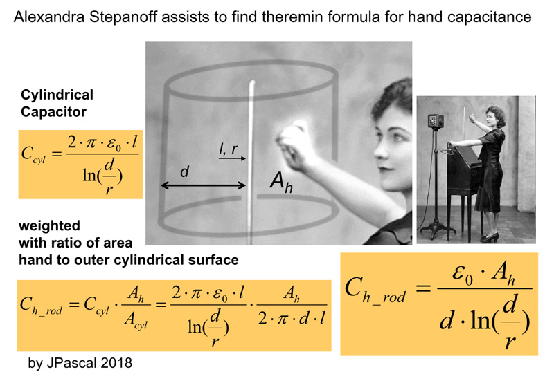
After searching many of published material I did not found anything reliable about this topic. Physical formulas to calculate capacitance of rods, plates ore between them overestimate the capacitance because they always assume, that the whole electric field consists only between them. No experiment validates such fomulas in the far distance. However, plate to hand area gives better results as rod section to hand area.
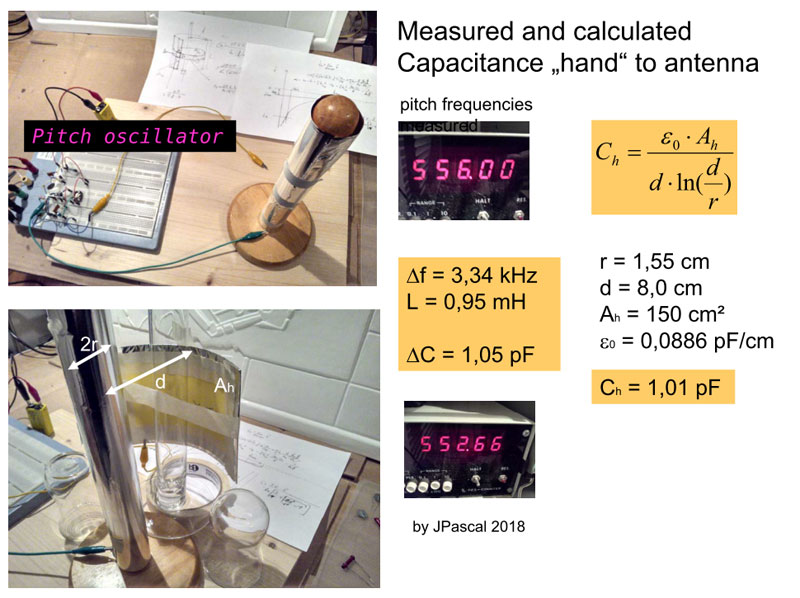
So I try to make another approach for longer distances. An old theremin grand dame is supposed to help me soon.
basic experiments
Posted: 1/27/2018 12:26:12 AM
Posted: 3/12/2018 6:46:27 PM
Now comes the next step to confirm the formula. Before I start, I will make a trip to another simplification. The well-known resonance formula is:
If the decrease of the frequency due to the hand capacitance is very small compared to the oscillator frequency itself, you can use approximately the first derivative:
Just a few cm and more away from the rod antenna in most cases an error results of less than one percent. That is, the audio frequency (pitch) is strong linear to the hand capacitance. The pitch range (octaves you get) is deteremined by the frequency of pitch oscillator - and proportional to it.
Posted: 3/15/2018 10:26:18 PM
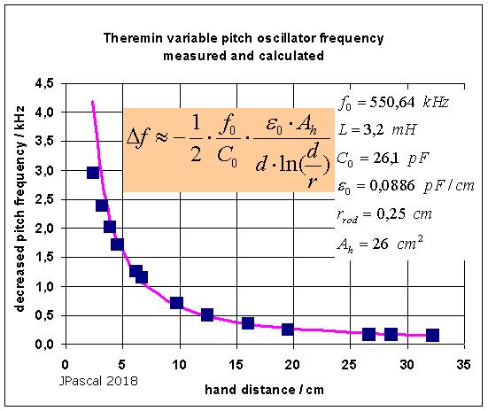
Ah is the front area of the conductive surface (hand) in direction to the rod antenna. I used my "one liter bottle" results from previous experiments and varied Ah a bit to fit the curve. The overestimation near the rod is recognizable because the front area is not concave, as assumed in the cylinder-based formula. I think its still pretty good.
In the next topic I will address the question of the true role of EQ coils and their influence on pitch frequency.
Posted: 3/17/2018 11:02:05 AM
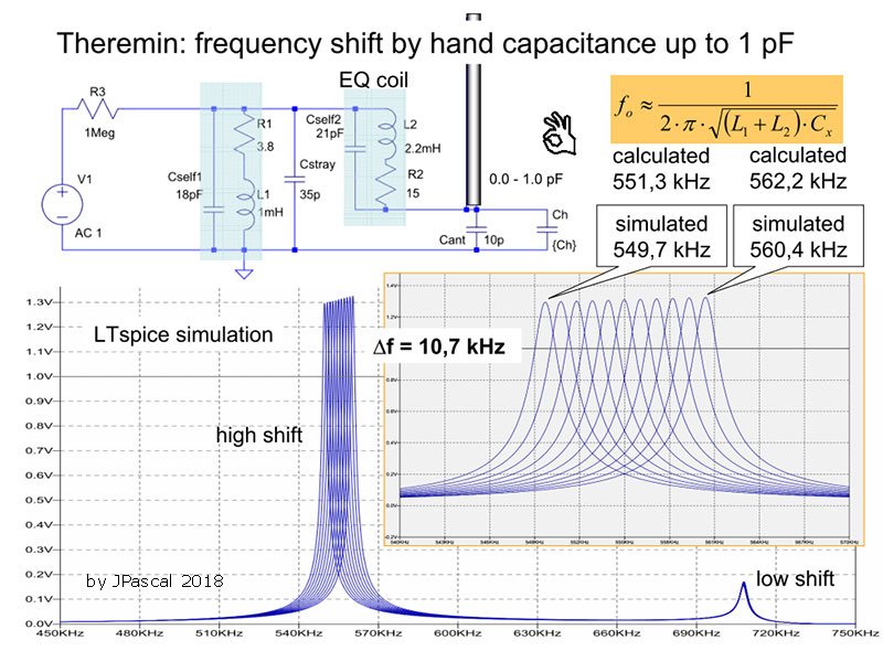
What is the advantage using an additional linearization-coil for the pitch oscillator? I give a simple explanation here. Without active electronic elements necessary for oscillator condition some importend L and C estimate the result mainly. C1 may contain more C resulting from transistor or tube.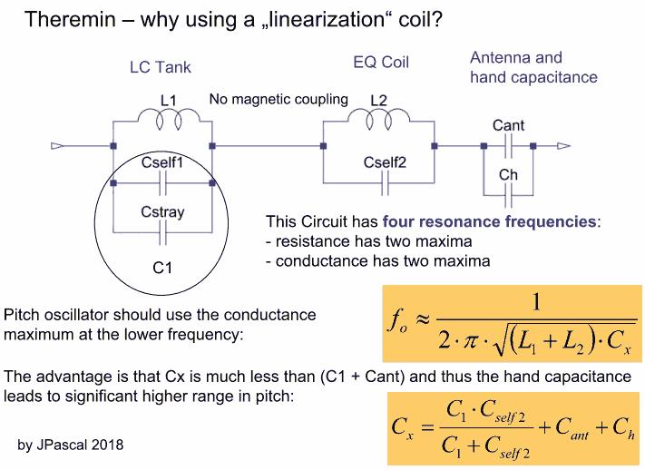
Posted: 3/20/2018 9:08:26 PM
The sum of inductances L1 and L2 (if not magnetic coupled) and their resulting parallel capacitance determine the proper pitch oscillator frequency. Here please find an excel calculation. Of course can also be done a LTspice simulation.
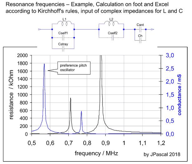
But how much is the down shift of all the resonances in case of a definit hand capacitance for example of 1 pF? How is the effect on pitch linearity by using the "linearization" coil? Next question, answer is coming soon.
Posted: 3/24/2018 10:12:02 PM
Now please find a LTspice simulation. The values for L, C, R are from real coils I use for tests. In fact the possible frequency spread is higher with a linearization coil, here about 11 kHz due to additional hand capacitance 1 pF. But theremin pitch linearity seems to be not enhanced. Dispite the lineariziation coil a strong linear dependence further exists between frequency and hand capacitance. This was variied in steps of 0.1 pF.
Next task is the effect of other capacitances like body or in series to antenna.
Posted: 3/24/2018 10:44:04 PM

Sorry to post on your thread, but I'm not seeing an LTSpice link? And I'm not clear on what's going on with the hand capacitance input: are you using real measured distance vs. C here (or a good approximation)? 21pF across the EQ coil seems like a ton of C, and the EQ coil L is normally quite a bit larger than the tank L (hundreds of mH vs uH).
Posted: 3/24/2018 11:38:10 PM
It's LTSpice IV. Input is parameter Ch. (step param Ch 0p 1p 0.1p). Coil data (fixed inductors) are correct so and both resonances can be shown in one diagram. There is no need for hundreds of mH. But I would like to test other data if you give me your prefered ones for my simulation. Normally some coils in series are used to reduce the self C.
What is the effect of the body capacitance and a capacitor in series to the antenna? Is than the audio frequency versus hand capacitance not strong linear? Here are the results from LTspice.
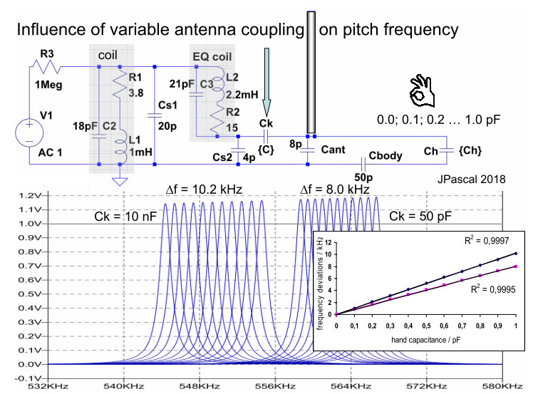
Very large coupling C 10 nF has here near zero impedance like direct galvanic connection without it. Coupling C 50 pF shifts the oscillator frequency und makes the pitch range smaller. Body capacitance is also choosen 50 pF.
With and without coupling C the hand capacitance is also here strong linear to the audio frequency.
You must be logged in to post a reply. Please log in or register for a new account.