"I've played a bit with your oscillator version in LTSpice, and tried to make it work in linear mode." - Vadim
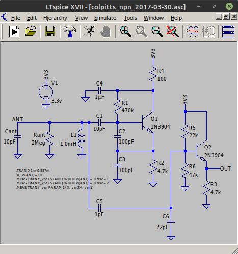
Examining your changes, you removed Rant (2meg) which isn't a real component but models antenna emission losses. You have to use this to approximate real swing at the antenna, otherwise you will get an unrealistically large swing in simulation. And sometimes the 2meg completely swamps oscillation in simulation, which is one clue as to whether you have a viable oscillator or not.
You increased R2 from 4.7k to 47k, which reduces the tank drive quite a bit, so the circuit is much more dependent on Q to get a large swing. If it oscillates at all in reality, you will see a large decrease in amplitude as your hand approaches the antenna, and oscillation will probably stop before your hand touches the antenna.
If you want spectral purity you should be buffering the tank swing itself via a capacitive divider. 1pF from the antenna to 33pF (change this to get the amplitude you want) to ground, pick off the intersection of the 1pF and 33pF and you will see a much nicer sine wave.
There will always be some discrepancy between simulation and reality. Usually the simulation works better than reality, often to the point where the simulation oscillates and the reality doesn't. I've found that I have to test circuits on a breadboard to get the full truth. This helps me fine-tune the parasitics (Rant and inductor DCR) to make the simulation better match reality.
"It is powered from 5V, but I believe it should not affect SNR."
Increasing the supply voltage is one way to increase the antenna swing, but I've found that I can usually get a sufficiently large swing with lower supply voltages. 5V is usually available, and regulating this down to a very stable 3.3V can give a very stable oscillator. I don't think I'd want to power these oscillators off of a shared, digitally noisy, and relatively unregulated 5V supply. Voltage regulation is an extremely effective and inexpensive way to obtain oscillator stability.
"Yes, it looks like transistor based oscillator is much better."
I don't necessarily agree. You can make a nice oscillator with CMOS, but most people don't for some reason. Could you post your CMOS oscillator in LTSpice format?
"My recent idea: if there are two (almost) sines - from variable pitch and reference pitch oscillators, why not build heterodine based on analog multiplication circuit. It should produce much better results than Add-detect-filter, or XOR schemes."
Yes, multiplying real sines is a much easier filtering scenario, but getting an analog multiplier to work at these higher frequencies is problematic. Moving your operating point up in frequency also separates the images more.