Tuned Coil Theremin Antenna Design

Posted: 6/24/2017 10:15:45 PM
oldtemecula

From: 60 Miles North of San Diego, CA

Joined: 10/1/2014

- The Week TW Stood Still -

I have long been a promoter of a tuned coil theremin antenna design. This could be the future of the theremin but its application has not yet been fully realized. What gets in the way is Moog worship and digital thinking.

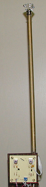
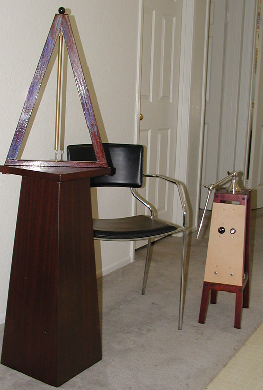
Pictured is a simple combination that will develop a wonderful natural theremin voice with an ideal linear pitch field right up next to the antenna. Drift is a non-issue due to balanced circuit simplicity. This antenna method works perfectly with a tube/valve Hartley pitch oscillator or NPN oscillator. The antenna is composed of a tightly coiled spring pulled slightly apart by the tuning jewel on top. This is a broadly tuned phenomenon so there is no need for linearizing inline antenna inductors. The coiled antenna is the inductor.

Always get a sound sample to validate any design or designers skill, some folks just talk talk talk, this is not a cheap digital whistle. sample.mp3

One engineer dared to explore, many people if they cannot Model something on their computer are crippled and cannot conceptualize an original idea. Last year my design was called the Lev Antenna, now it will be called the Altermen Pitch Electrode "APE" out of respect. 

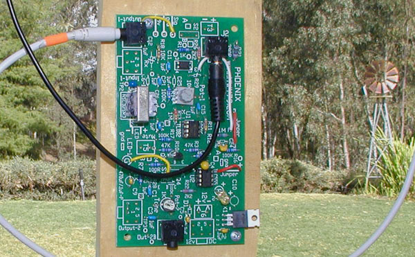
Looking at the PCB below, the theremin concept really is that simple, just two RF oscillators. Speaking of Apes some monkeys have this weird need to make something more complicated than it actually is, this is a side affect of not being able to mate, if you challenge them they throw poop at you. surprised

Christopher


Posted: 6/25/2017 3:12:28 AM
shadmock

From: Los Angeles, California

Joined: 2/27/2017

That sample sounds great! Retains some of the buzz of the old school Theremins.

Looks like a very simple circuit?

Is the tuning jewel a specially fabricated piece? 


Posted: 6/25/2017 4:59:48 PM
oldtemecula

From: 60 Miles North of San Diego, CA

Joined: 10/1/2014

shadmock said: "Is the tuning jewel a specially fabricated piece?"

Actually the knob is a threaded drawer knob. On top of the triangle below you can see another knob version. I made this theremin design for a wounded warrior musician that had lost an arm. He used his knee for volume control and did not want his picture taken.

Christopher

Posted: 7/3/2017 1:35:41 AM
djmartins

Joined: 3/8/2006

I like those two theremins, I bet the vet appreciates what you did a lot and it looks pretty nice too!

Interesting design, both pitch and volume.

How are the two parts connected?


Posted: 7/3/2017 3:36:04 AM
oldtemecula

From: 60 Miles North of San Diego, CA

Joined: 10/1/2014

Hello djmartins,

Both Pitch & Volume use the same PCB layout, just a slightly different arrangement of components. I connect the two pieces together using a 12' 3.5 mm TRS Jack and cable. In the photo it is the black cable. The cable transfers power and line level audio to the opposite unit. Missing from the photo is the 3" x 3" RF section. My Harmonic Exciter PCB was modeled after what you see. Schematic wise they are identical. The sound I like, was eventually figured out by using the audio transformer. The chips are a LM358 & 555.

I have never done computer modeling, I don't think I could have found the sound that way.

After 15 years I have reached all my theremin goals and slowly retiring from it all.

Christopher

You must be logged in to post a reply. Please log in or register for a new account.