


After playing hours and hours with the pitch oscillator, I've decided to rename my 32bit Theremin project. New name:
![]()
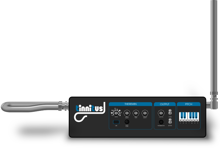
Today I've released the first version of my STM32 theremin.
Last week a 15 years old student has built up this theremin with my help and she has programmed the pitch LED display.
The project website is:
https://github.com/gerdb/tinnitus32
Sure enough if someone just messes around year after year someone else is going to beat you there with something even better. Now why can I not find a sound sample anywhere, maybe not looking in the right place. Is it a toy or is it amazing?
ILYA, I doubt any kind of display is useful for a seasoned Thereminist as play is more spontaneous, just my opinion.

I believe you will face with issues while try to measure oscillator frequency with MCU.
Heterodyning on D trigger will help a bit, but it will introduce aliasing.
You will need to use filtering of measured signal periods which will provide trade-off between latency and sensitivity.
No problems with short distances between hand and antenna. But to get good sensitivity for long distance, you will need to do averaging of a lot of measured periods, which would lead to latency.
I'm afraid you will get crap-like sensor behavior like in Theremini.
I'm working on FPGA based project which will be expensive ($200 for FPGA board and $50 for touch screen), but require less of soldering.
Zybo Zynq Z-10 as main board
Stereo audio input/output 24 bit, 48 KHz
HDMI output
USB Host
1Gb of DDR will allow to implement rich effects like recording / loops.
There are two ARM cores available.
1st core will be used for GUI and common control functions
2st core may be used as dedicated DSP for algorithms which are hard to implement in FPGA
7" hdmi LCD touch screen (touch support via USB HID).
Touch screen based GUI
I've implemented lightweight HDMI controller which implements DMA internally and utilizes about 500 LUTs (unlike HDMI interface provided in examples).
Theremin sensor implemented in FPGA as AXI (uses about 1000 LUTs, 2 DSPs, 4 BRAMs)
Oscillator frequencies will be measured directly w/o heterodyning - two digital input pins required - one per oscillator.
Change of antenna capacity gives about 5% of frequency change
ISERDES in DDR mode + oversampling based on delay lines provide value of signal period with 14-16 bits meaningful bits (equivalent of frequency measure with 12-16GHz measurement period). Period value is updated on both signal edges.
Averaging filter - increases number of available bits
Scaler - based on min and max frequency preset, converts frequency value to 0..1 range (24 bits)
Linearizer - converts frequency to distance based on lookup table (1024 entries)
Distance to note and note to signal base frequency period converters - for pitch only - lookup table based (as well can be used for pitch correction, etc)
Sensor Controller provides ready to use volume and note/phase increment values once per sample.
Scaler parameters and lookup tables can be modified from CPU.
Measured values are available for CPU as memory mapped registers.
A lot of FPGA and PS(CPU) resources are available for DSP / synthesizer implementation.
Touch screen GUI will allow even to implement instrument editor as a part of theremin software.
Current problem I faced is a lack of standalone USB host implementation which is needed for touch screen HID device support.
Hello Buggins,
>I believe you will face with issues while try to measure oscillator frequency with MCU.
..
>you will need to do averaging of a lot of measured periods, which would lead to latency.
I've chosen an oscillator frequency of about 500kHz. It is divided internally through 8, so i have about 62kHz. Then I measure the period time with the core frequency resolution of 168MHz.
So I can measure the period with a resolution of 2688:1
I then do an oversampling over 1024 periods so I finally have a 22bit pitch value with a resolution of 1:2752512 and a time constant of 16ms.
Assumption: If the frequency variation of the oscillator is 1%, I would have an resolution over the 50cm pitch range of:
0.02mm with a 16ms filter
or
0.3mm with a 1ms filter
Hello Buggins,>I believe you will face with issues while try to measure oscillator frequency with MCU...>you will need to do averaging of a lot of measured periods, which would lead to latency.I've chosen an oscillator frequency of about 500kHz. It is divided internally through 8, so i have about 62kHz. Then I measure the period time with the core frequency resolution of 168MHz.So I can measure the period with a resolution of 2688:1I then do an oversampling over 1024 periods so I finally have a 22bit pitch value with a resolution of 1:2752512 and a time constant of 16ms.If the frequency variation of the oscillator is 1%, I would have an resolution of the audio frequency of 15bit.
Let's hope 15 bits is enough for far hand distance.
BTW, you can try to change oscillator - to get bigger variation (about 5%).

You must be logged in to post a reply. Please log in or register for a new account.


