(Yet another) Tube theremin project

Posted: 11/14/2018 1:22:57 AM
voretaq7

Joined: 11/13/2018

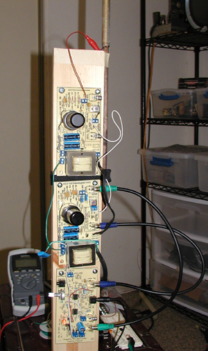
For my winter challenge project this year I’ve decided to build a tube Theremin staying reasonably close to the RCA/Lev-built designs ca. 1930 while using new/current production vacuum tubes and other parts. As this happens to be the most active hive of theremin enthusiasts I’d like to get some feedback from those of you who have done vacuum tube theremin builds to see what you all think of my plan and it’s feasibility.

Background
I'm a tube amplifier guy who has dabbled in radio work so most of the concepts in the theremin are familiar to me. I'm 100% confident I could build a functional instrument using period tubes & schematics so the "challenge" part of this project is more along the lines of building the device using tubes you can buy off the shelf at your local guitar shop rather than hitting up eBay or similar to grab some of the ever-dwindling stock of NOS tubes vital to folks who have original-era instruments.

In preparation for this project I've studied the documentation on the RCA theremin & the customized Rockmore theremin as well as some of the modern tube efforts like Art's 126 Theremin. Based on that and my own notes I've got this project to the "incomplete on paper" stage - I know roughly what each section of the project will look like but I don't yet have a complete schematic showing how the whole thing will go together because there's some experimental wiggling to do yet.


Power Supply
I am unashamedly cheating with respect to the power supply design: Everything will be solid state here. I've built my share of tube pwer supplies but an analysis of the RCA & Rockmore schematics leads me to conclude that power draw is unlikely to vary enough for tube rectifier sag to make a noticeable difference in the final tone of the instrument. A solid-state power supply will be faster and cheaper to knock together.

I am sticking with the original RCA/Lev concept of a split chassis however, so if someone wants to go with a tube power supply they can construct one and drop it in to the design.

Oscillator Circuits
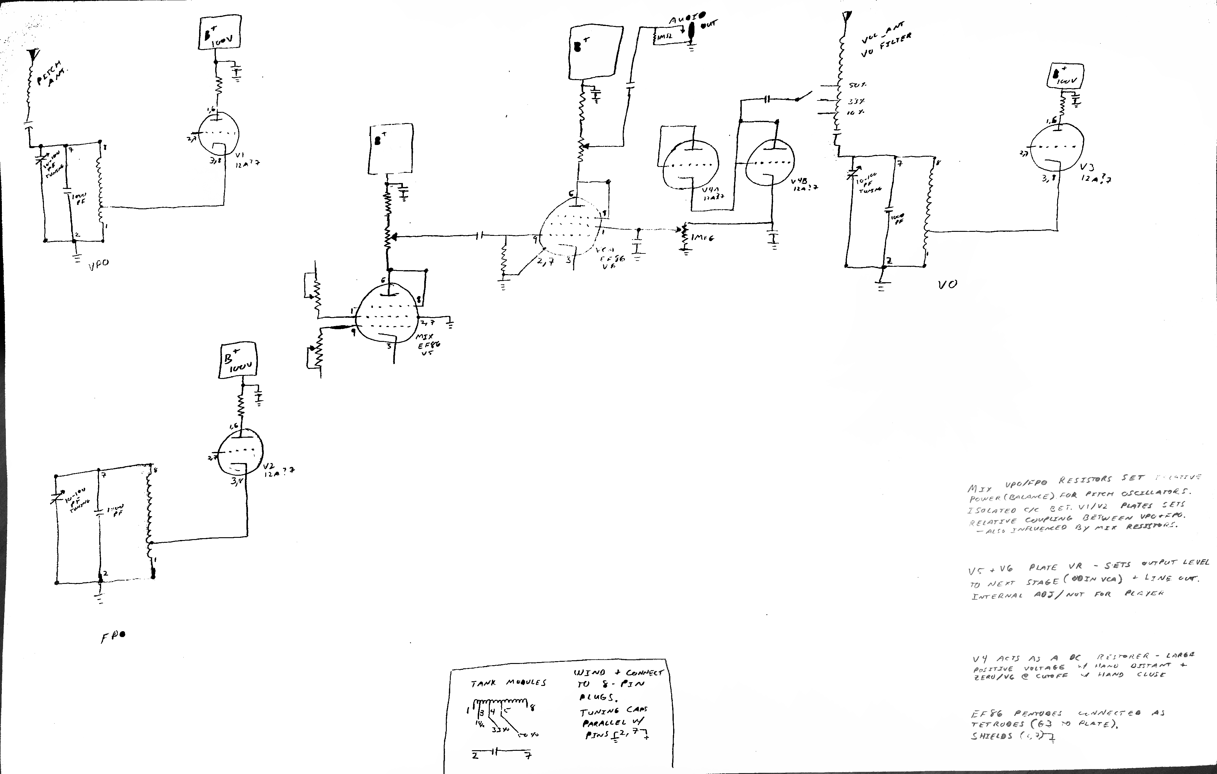
I plan to use a separate 12AX7 for each of the 3 oscillators, with both sections connected in parallel so the tube effectively functions as a single triode. Separating the pitch oscillators in this way is necessary to prevent capacitive coupling between the 12AX7 sections (I bench checked using one tube to serve as both FPO & VPO with poor results), and there's no good reason not to construct the volume oscillator identically.

Rather than the tuned plate Armstrong oscillators used in the original design I'm opting for tuned grid Hartley oscillators. This should be a distinction without a difference save for making the oscillator coils somewhat easier to wind and having the overall circuit be less twitchy and more tolerant of any poor construction on my part.
Operating frequencies will be derived from the RCA spec (170ish KHz pitch, 400ish KHz volume).

Mixer Circuit
The closest modern equivalent to the 27 tetrode would appear to be an EF86 pentode connected as a tetrode (G3 tied to the plate).
I'll be lifting the mixer circuit largely from the Rockmore theremin design, including the balancing potentiometers & variable coupling capacitor between the oscillator circuits. 

Volume Control & Power Amp
Here is where I and every modern designer will be forced to break with the traditional designs: The clever variable filament power design used in the RCA themin is largely impractical today even with custom transformer winding as directly-heated (filament cathode) tubes are a rarity these days. Similarly the equally clever solution in the Rockmore theremin of driving the audio preamp's plate from a (dual)diode's cathode would require some engineering abuses of modern production tubes that I'm not 100% comfortable I could pull off.

Art's approach of varying the cathode bias is an interesting one, and I've decided to take a similar approach via a different route: I intend to use a single-ended EL84 as the power amplifier and drive the screen grid from the volume circuit (bringing the tube to cutoff when the hand is near the antenna and allowing it to conduct as the hand moves away). This design uses an additional 12AX7 family tube as a rectifier & DC restorer, feeding an essentially zero-current load on G2 of the EL84.

Variations of this approach have been used in tetrodes for other applications, though as far as I'm aware this is an untested application in the EL84 (or any beam power tube) and it is off the datasheet / not modeled in any of the tube software I have so this is going to be much of the "experimental wiggling" I mentioned. A direct lift of Art's design for the voltage-controlled amplifier is also an option should my clever twist here fail to work as desired.

Power output will be through the aforementioned EL84 (single-ended, around 10W audio output). This is somewhere between the ~0.75W you can squeeze out of the RCA's single-ended 171A and the ~15W I estimate the Rockmore circuit could produce with its push/pull 59 tubes.


That's where I stand as of this evening - looking forward to questions/comments/concerns.

Posted: 11/14/2018 3:20:12 AM
oldtemecula

From: 60 Miles North of San Diego, CA

Joined: 10/1/2014


Hello voretaq7,

The last thing I would ever want to do is get in front of any theremin builder’s learning curve. After reading your ambitious goals the main thing that I would suggest is to make the pitch section operate at 900 kHz for some very simple and practical reasons. It is through vacuum tube design I originally found the classic sound that I was after but it also showed me the method to use with transistors.

I think of the classic theremin sound as an illusion or even a trick in the hands of a Master. There are several unique theremin phenomenons you will discover as you go along.

I had a friend, Paul Tanner that somehow made the world think, by accident, the theremin was supposed to sound like a cheap whistle. Since his passing I feel a need to remind people of what the authentic theremin could sound like.

I have not picked up a soldering iron for several years and recently decided to again build my solid state approach to the pitch section so I could share it with my friend in St Petersburg Russia and sure enough the theremin always wants to kick my ass and not come easy. I will get there.

I have bad hearing but here are two samples of what I think a classic theremin wants to express.  Sample1    Sample2

When in Walmart my granddaughter wanted me to buy her a Theremini so she could practice alongside me and I told her that would be like Barbra Streisand singing a duet with the digital voice of Steven Hawking. (RIP)

Christopher

Posted: 11/14/2018 4:14:25 AM
dewster

From: Northern NJ, USA

Joined: 2/17/2012

voretaq7, you're miles ahead of me on the tube stuff, and it will likely stay that way as my interests are on the digital side of things - unless I build one around an Eniac!  But generally, in the early stages I'd recommend not being concerned at all about cabinetry or appearance in any way, get it all totally working to your satisfaction before even thinking about the final look.  The physical design stuff just gets in the way / ties your hands in the beginning.

Posted: 11/14/2018 8:19:59 AM
voretaq7

Joined: 11/13/2018

Hi Christopher,


After reading your ambitious goals the main thing that I would suggest is to make the pitch section operate at 900 kHz for some very simple and practical reasons.


I'm curious what practical reasons you're referring to for setting the pitch oscillator at a high frequency, especially since coincidentally my test apparatus where I determined the feasibility of the 12AX7 VPO circuit is running at 1MHz. (In my case that was chosen out of laziness and convenience - I haven't yet wound the large coil for the antenna circuit so I used the other pitch oscillator coil as the "antenna" coil. The native resonance of the pitch coils works out to around 1MHz, giving excellent frequency response when I connect the bit of wire I'm using as an antenna through the other coil - significantly better than connecting the antenna directly to the oscillator's tank circuit).


Certainly a pair of 1MHz oscillators would work well based on my bench test, but If I'm right on the theory it seems any pitch oscillator frequency (within reason and avoiding harmonics of the volume oscillator frequency) should work provided the antenna circuit (coil) native resonance is closely matched to the frequency of the oscillators so the relatively small changes in hand capacitance strongly influence the antenna circuit's resonant frequency and thus the VPO's frequency.

The other major variable in the pitch circuit design would seem to be the sensitivity of the pitch tuning control (approximate Hz/pF) on the fixed pitch oscillator, with it being desirable to set this to a "reasonable" value based on the tuning capacitors used (in my case I plan to use 100pF tuning caps so oscillator tanks on the order of 100-200Hz/pF would probably allow more than enough tuning range without being too "twitchy" on the control knob.

Posted: 11/14/2018 3:47:45 PM
oldtemecula

From: 60 Miles North of San Diego, CA

Joined: 10/1/2014

voretag7 are you in the states?

I do not speak engineer-eeze and only a theremin authority of my own research. Most likely you are already aware of my theremin WebPages as all the search engines have me on page one except google because there is no profit in it for them.

My main emphasis is to have your final unloaded pitch oscillators operating between 900 kHz to 922 kHz which 9/22 is Michael Faraday’s birthday. You bench test which is wonderful as there is a mystical side to theremin design that is hidden from those who only Computer model.

The image below is hard to make out but I am using the same Hartley Oscillator configuration and IF coils that I use with my transistor design.

This was my first basic approach without using any exotic coils. It had a perfectly linear five octave pitch field with no bunched up musical notes next to the antenna; it is thermal drift free and has the classic sound of Clara. All of this comes about from just a little bit of knowledge which you will discover over time. This knowledge cost me $10,000 over many years to gain and I have always given it away freely. The goal is to explore and have fun while doing it.

What I also find fascinating is my transistor oscillators operating at 9 volts have over 150 v pp on the antenna measured using a 10:1 probe on a scope along with a perfectly linear pitch field which is another mysterious theremin phenomenon.

On my early tube designs I use optical tuning instead of a variable capacitor so tuning could be placed anywhere, even across the room.

Christopher


Posted: 11/15/2018 11:58:06 PM
voretaq7

Joined: 11/13/2018

I am indeed in the states (Snowy New York).

Re: Oscillator frequencies, the one concrete advantage I see in operating at higher frequencies is that the antenna resonant coils could be somewhat smaller (less inductance required to match with the hand/antenna capacitance to reach the desired frequency).

Ultimately changing oscillator frequencies later is easy enough - I'm planning to use plug-in coils for the oscillator tanks (the "little coils") and can add the tank capacitance in the same module. That may require an additional chassis trimmer cap to fine-tune the frequencies (I was only planning one to set the fixed pitch oscillator frequency and one for the volume oscillator frequency, but thinking on it having a trimmer for the variable pitch oscillator to allow both it and the FPO to be adjusted to resonance with the antenna circuit makes logical sense as it would let me adjust for antenna coils that don't precisely meet their theoretical design specifications).
The Rosen and RCA theremin schematics do not show such a trimmer, but the Rockmore theremin schematic has one presumably for exactly this purpose.

Re: My bench test, this is running on my low-power (6-12V plate & filament) system which is left over from a previous project (a battery-operated tube preamp) so its results are obviously not entirely representative of a system running with realistic B+ voltages - among other things there's no stabilization of the power supply beyond what my little regulated 12V wall-wart offers.
In this configuration my mock pitch section is managing about 15-20V at the 6-inch wire that's playing antenna (measured with a single-loop pickup), with an effective pitch modulation range of about 12-16 inches. A proper pole antenna with real voltage going to it will, I suspect, behave better.

Undecided at present is where to tap the signal for the mixer (I can get a perfect sine wave off the tank or a tube-distorted one at the cathode; a plate tap is not an option since at 12V I can't afford a plate resistor of any meaningful size but that will be an option in the final high-voltage version).
Tapping at the plate or cathode will not add further capacitance to the resonant circuit which is desirable, though series resistors between the oscillators and the mixer grids (in keeping with the Rockmore & Rosen designs) would limit that loading.

I am growing fairly comfortable with the core design and will probably sketch schematics (or at least a block diagram) at some point this weekend to share for thoughts. At the moment the issues I'm puzzling over are getting power from the "power supply chassis" to the "instrument chassis." (probably an 8-pin tube socket on either end & a tube-plug cable for simplicity's sake) and whether I want to build a power amp/speaker level output vs. something at a low line level that gets fed to a power amp later (essentially a choice between the EL84 and another EF86 as the "volume" stage).

Posted: 11/16/2018 2:02:13 AM
oldtemecula

From: 60 Miles North of San Diego, CA

Joined: 10/1/2014


voretag7, you are entering an interesting and fun journey. There are three main characteristics of the theremin that fascinated me the most. First would be the Classic Theremin Sound, next is having a perfectly linear pitch field and then how is my solid state approach thermal drift free. There is something magical that happens at 900 kHz which is too mystical in how it came about to explain it now.  I will be sending my circuit board with these qualities to St Petersburg Russia by Christmas so a Thereminist friend can share it with the great grandson of Theremin himself, let him decide if I am simply crazy or was given a special piece of Theremin knowledge. He reads this forum regularly so this is a subtle message for them.

I do monitor your weather daily as I adopted an afghanistan veteran, who I only met once, with three kids under five a couple of Christmas’ ago. He now lives in Gaithersburg MD. This gets me things like videos of the kids getting on the bus for the first day of school, first shots in the arm and today they had it off for their first snow day. I thought doing this act of kindness would improve my results in the stock market and so far I have not been that lucky. LOL

Enjoy your theremin build, I am not the brightest bulb on this board, there are others, no…. you will mostly be on your own.

Christopher

PS: dew to hear your voice makes me think you are human, I apologize if ever I seem difficult.

Posted: 11/22/2018 4:16:11 AM
voretaq7

Joined: 11/13/2018

Hark! An update!

After some assorted jiggery-pokery with my bench rig and subcircuit SPICE simulations I've come to a more-or-less final design: The missing elements are ones I can't simulate or throw math at and will have to work out on real hardware.

Because of constraints on the availability of components (specifically power transformers) my plan to drop an EL84 into the design had to be scrapped - I don't want to pay for a custom transformer wind & the best option in EDCOR's standard parts list is the XPWR057 which really can't support a full compliment of 12AU7s, an EF86, AND an EL84 on the HT supply. (I could add more solid state elements to reduce the load, but part of my challenge to myself is to do at least the whole audio/instrument chassis with tubes.)
Because I'm going with the 057 transformer I also get a 5V filament supply, so the power supply will likely be one of my tube-rectified designs (I have a bunch of #83 rectifiers here, I may as well use them). To stay within the power limitations of the transformer I'll be using a second EF86 pentode as the voltage-controlled amplifier and generating a high-Z output signal somewhere between instrument and line level to drive a separate amplifier, but the control principles remain as previously described.


I had intended to scan in my sketched schematic at work on a printer that can swallow 11x17 paper but alas I left it on my bench at home. Instead I offer a bad iPhone photo of the working sketch and notes. ("Please excuse the crudity of the model. I did not have time to build it to scale or to paint it.")

Any component values here are tentative and represent just what I've tested with on the bench, or spitball numbers that "should" work but are by no means final. 

Also note that many elements are missing/not drawn. Among other things the pitch oscillator tanks are not connected to the oscillator tube grids in this drawing so they won't actually oscillate. (I have not decided on the final configuration here - I may simply connect the coils directly to the grids). The oscillators are also not shown connected to the mixer stage input resistors (this connection would most logically be made from pin 8 of the oscillator tank and/or the grid pins of the triode, but there are other options such as putting a larger load on the plate and taking the signal from three). Capacitive coupling between the pitch oscillators as is present on the Rockmore theremin is also not shown (the logical place for this would be in the oscillators' plate circuits, which requires either a fixed capacitor or an isolated/ungrounded air variable capacitor).
Configuration of these elements will be determined experimentally as I expect simulation is unreliable for these items.


Configuration of the EF86 pentodes (particularly the VCA) are also not final and will have to be determined by experimentation at working voltages. What's shown here are generic "Should Work" configurations for theoretically perfect pentodes. As they are untested they may not work (and may even damage real world tubes - I have no idea of the suppressor grid of a modern EF86 will handle being tied to the plate & constant small current flow without melting). 

Note also that the EF86 cathodes will need to be grounded, but likely not directly grounded (there will likely be some resistance between the cathode and ground to set a reasonable bias point as well as some cathode bypass capacitance in at least in the VCA. Per Bob Moog's notes the mixer tube in classic era Theremins is appropriately biased by its own capacitance and the large negative voltage swings which keep the tube at cutoff at least 50% of the time, but this configuration may need a cathode resistor in the mixer stage as well. Such an implementation would color the tone coming out of the mixer tube).


Posted: 1/26/2019 10:29:59 PM
voretaq7

Joined: 11/13/2018

Hark! An update!

The best laid plans of working on this in late December fell apart due to home renovations, but I have not abandoned the project!

Most of the components have been purchased and are sitting on my bench. The power supply is assembled and tested - in the interest of flexibility for the  I kept the voltages high (280V) which may require reducing the voltages in the instrument chassis (or I might redesign the step-down in the instrument chassis), but I'll burn that bridge when I drive over it.

The instrument chassis is drilled and I'll be installing the sockets this evening (Photos to follow). New LC tanks will get wound either tomorrow or Monday (I need to cut new PVC forms & wind replacements because my experimental test coils did not include the capacitor as part of the tank (on pins 2/7) so the pinout has changed. Once I have those I can start wiring this pig up for testing.

Project files are up on github (https://github.com/voretaq7/theremin) and the current state of work is available in PDF form here as a pre-release.

Things I still haven't worked out:

Aside from the notes on github about what isn't done yet:

I haven't designed the Pitch or Volume antenna coils yet. There's math involved here.
I also haven't decided on how those are going to attach to the chassis or antennas. Probably going to be banana plugs on stranded cables.

I haven't selected antennas yet. I'm going to try to find replicas of the classic Theremin antennas, otherwise I'll need to fabricate something for testing purposes.

Posted: 2/19/2019 11:17:19 PM
voretaq7

Joined: 11/13/2018

It lives, it oscillates, it heterodynes… sort-of.

I've got the pitch oscillators built and working (at ~175KHz which is right about where I wanted them). I'm able to get a heterodyne frequency between 500Hz and a few KHz using a quick-and-dirty jumper wire build & bit of wire hanging off a coil in this configuration

The problem is I can't get much lower than that: The oscillators are coupling together & falling into sync at anything below about 500Hz difference (the beat frequency goes away and they start messing with each other's amplitude). This does mean that I don't need the oscillator coupling capacitor as noted on the Rockmore Theremin schematic, but it's also WAY too high a zero point for a practical instrument.

I suspect this is oscillator tube / coil RF coupling: There's not much noise on the power supply rail (currently that's dropping through 20K ohm wirewound resistors that are acting as decent RF chokes), but my current layout has the two pitch oscillators next to each other with their coils both oriented vertically (wound on octal tube plug-in forms) & their trim capacitors next to each other. Having the coils oriented along the same plane is probably contributing to the over-coupling, and the proximity of the 12AX7 tubes & variable capacitors is probably doing me no favors either.

Tonight I'll be looking at reducing the standing RF (tapping the Hartley oscillator at 25% or 10% to reduce the "kick" current & voltage in the tank). Failing that I'm left with either shielding the coils or reorienting the reference oscillator's coil so the magnetic fields are at right angles (this last option would be difficult without moving to a larger chassis).


If anyone has data on tank voltages & coil distance limits I'd love to compare notes.

You must be logged in to post a reply. Please log in or register for a new account.