Burns B3 Guts

Posted: 4/26/2019 2:55:30 PM
dewster

From: Northern NJ, USA

Joined: 2/17/2012

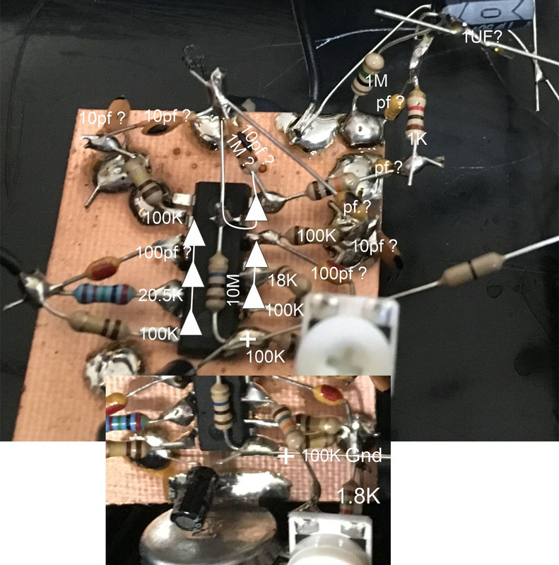
I'd previously encountered one or more pictures of the internals of the Burns B3 elsewhere on the web, but couldn't locate them again lately via various web searches.  Recently TW member Spiratonic graciously posted two pics of the internals, which I then stuck in a TW photo album [LINK] so we all get to see what's in there:

The "dead bug" layout looks super labor intensive to me for such a simple circuit.  I would think a PCB would be the order of the day for a product listed on Amazon.  IMO, anything based on CMOS should socket the ICs - good luck repairing this!

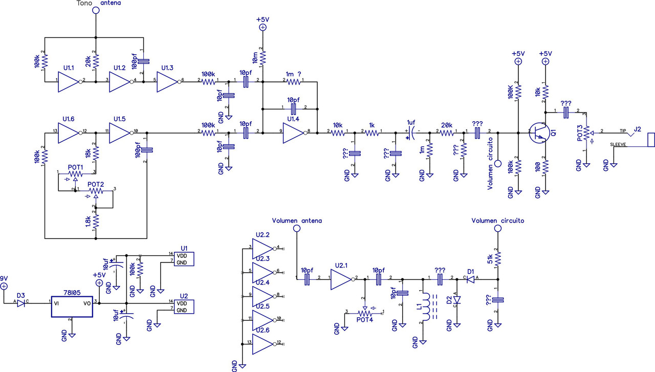
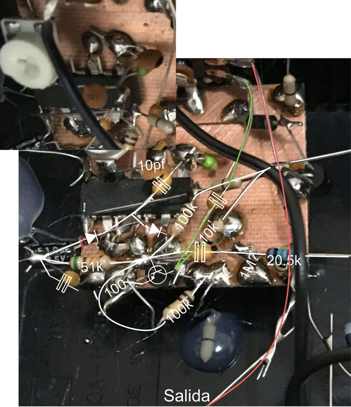
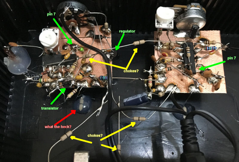
The more I look at it the more I'm pretty sure its CMOS inverter based because of what looks like 14 pin DIPs with many adjacent pins connected together (thus chaining inverter I/O), and you can see one corner pin (7) on each is clearly ground supply, with the opposite corner pin (14) clearly positive supply.  There are two TO-92 packages, one is obviously a voltage regulator because it's fed by a rectifier coming from a separately elevated portion of the PWB which is connected to the pot power switch.  The things that look like resistors with a single band down the middle could be chokes of some sort, but I only see them in what appear to be power feed and audio RF filtering situations, so probably no LC resonance going on.  

There's a mysterious component with one end grounded, the other end apparently missing, with the whole thing embedded in a gob of silicone?  [EDIT] There's on on the other board too!  Looks like a jury-rigged board support.

Anyway, without a longer & better look at it, I'd say it's an RC CMOS Theremin.

Thanks again to Spiratonic for the pix!

Posted: 5/1/2019 1:12:49 PM
Valery

From: Russia, Saint-Petersburg

Joined: 6/6/2016

 chokes? - this is a resistor with zero resistance to connect the boards together.
In my version there is no element covered with a silicone cap. (This can be used as a grounding variant to the conductive base of the housing.)
 In general, the scheme is very similar to the well-known minimum theremin Harrisson, but significantly modified.

http://harrisoninstruments.com/100/100_schematic.html

Posted: 5/1/2019 2:40:01 PM
dewster

From: Northern NJ, USA

Joined: 2/17/2012

Thanks Valery!

I have no direct experience with RC Theremins.  What is the pitch field like?  

1. Is it bigger or smaller than an LC Theremin?  
2. Is it more or less sensitive (i.e. one octave per open/closed hand) than an LC theremin?  
3. Is it more or less linear than an LC Theremin?

Posted: 5/1/2019 5:42:16 PM
Valery

From: Russia, Saint-Petersburg

Joined: 6/6/2016

Hi, Dew!

1- B3 is quite small and light. B3 Deluxe is an elongated shape for removing antennas from each other. The body is made of extruded cardboard. The left antenna is made of brass-plated wire, and the right telescopic for coarse tone tuning.
2- Pretty sensitive. Although not perfect linearity. LС Theremin is better.
3- Linearity is not perfect. Although I played almost without rehearsals. The timbre of the instrument resembles a “slightly nasal voice.” The number of adjustments is minimal.
   In my opinion, such constructions have the right to life, since they are quite simple to make, but LC Thermins has a more interesting sound, and you can “invent” various forms of sound.
  This design is very sensitive to mains power. The best quality gives the battery charge and good grounding. Internal stabilizer B3 9 volts. (7809)

Posted: 5/2/2019 1:08:33 PM
dewster

From: Northern NJ, USA

Joined: 2/17/2012

"This design is very sensitive to mains power."  - Valery

I would imagine so.  High Q LC oscillators in a Theremin setting are in effect narrowband transmitters and receivers, so they reject a lot of environmental interference, such as mains hum.  RC oscillators let everything in the door, though you might be able to filter some if it out later via digital means.  Spread spectrum low Q LC or RC might be the best of both worlds.

Posted: 7/5/2019 8:52:06 AM
Goño

From: Guadalajara, Jalisco, Mexico.

Joined: 7/5/2019

Hola soy nuevo por aqui.
Mirando las fotos me surgió interés por la sencillez, el lado del tono lo tengo probado en el protoboar y funciona, con algunos cambios en la polarización del transistor.
El lado del volumen no logre ver algunas cosas por lo cual no lo he probado.

Posted: 7/5/2019 12:37:50 PM
dewster

From: Northern NJ, USA

Joined: 2/17/2012

Wow, Goño, thanks for that!

I believe your schematic shows the volume side working via 50/60 Hz hum pickup, rather than by using an oscillator?  If so, I would imagine that the range of operation would be quite short.

Posted: 7/5/2019 8:45:07 PM
Goño

From: Guadalajara, Jalisco, Mexico.

Joined: 7/5/2019

Dewster algo así pensé sobre la antena de volumen, pero sin mas fotos o una unidad para verificar es pura especulación lo que pongo en el esquema. 
Hay un condensador de colector a gnd y una resistencia de tip a gnd, no aparecen en el esquema.

 
Una imagen de los osciladores, el amarillo es el oscilador fijo, alimentados con 9V 

Saludos.

Posted: 9/4/2019 9:39:37 PM
edavid

From: Montana, USA

Joined: 9/2/2019

Wow, Goño, thanks for that!I believe your schematic shows the volume side working via 50/60 Hz hum pickup, rather than by using an oscillator?  If so, I would imagine that the range of operation would be quite short.


That part of the schematic is not quite correct.  I haven't completely traced the volume side, but U2 is a 74C14, and 1 section is used as the volume oscillator.  (I found it handy that the other sections were unused, when the first one was zapped by ESD.)

U1 is of course a CD4069UB.

The unit I have runs on 12V (from a 78L12 regulator).  Goño, are you sure yours runs on +5V?

Posted: 9/4/2019 10:00:12 PM
DanielMacKay

From: Halifax, Canada (east coast)

Joined: 7/28/2019

Yuck! What a MESS

You must be logged in to post a reply. Please log in or register for a new account.