Replacing the oscillators in the Etherwave Theremin?

Posted: 11/16/2019 5:19:17 PM
oldtemecula

From: 60 Miles North of San Diego, CA

Joined: 10/1/2014


Charm, 

so you want to build four Theremins by Christmas of 2020, which is 12 months from now? That is very ambitious; your learning curve will teach you why.

Like you twenty years ago I wanted to build my first theremin and only use the basic parts I could find at a chain store here called Radio Shack, why today my design uses basic parts. What did you expect to achieve by changing the EWS oscillator configuration, they are a solid design that I don't like.

I had some knowledge of electronics but had never worked in electronics, why I am not always clear in how I express things. I just learned as I went along.

I think the idea of a digital theremin is a dead end unless you like a whistle with latency, why no Theremin Professional plays one. 

Always get a sound samples of any theremin design you have interest as that is as good as it gets. I had my sound ten years ago but last Christmas is the first time I heard a Thereminist play my design. My Theremin project is an experiment that will evolve more, I have nothing to sell.

I like digital logic in its proper application and why once in a while I show people here that making money in the stock market which is all numbers is real. This is my Extreme Logic, over 10,000 lines of code behind an Excel Spreadsheet; to anyone with common sense you can see my favorite algorithms. This is this week 11.11.19  I think it funny people that always show code and no results. In mine you see no code, just $3000 profit in three weeks if you play a minimum amount.

As long as we are having fun that is most important.

Christopher  

Pitch Board L1 & L2 & L3 & L4 Need further explanation. Terminal ABCD is for minor waveform adjustment.

- Charm this should not be your first theremin build -

This is easy to follow, any more exchanges I need to remove myself from the digital swamp thinking

For better vocal, after studying the Thierrymin it would be fun to change L1 & L2 with fixed inductors and Pot-5 to a 5-20 pf variable cap.

dewster is perfect for your learning curve

Posted: 11/16/2019 8:26:13 PM
CharmQuark

From: Sweden

Joined: 11/14/2019

@dewster: Yes, I'm aware of OpenTheremin, but I don't like it for several reasons. As an professional AVR-programmer I can't help but frown upon arduino stuff (as you probably know, arduino is a dumbed down version of AVR that learns a new generation nothing about electronics and how to be a really bad programmer). Another reason is that I cant find anybody anywhere who plays the OpenTheremin satisfactory. Yes, loads of sound tests on Youtube, but nobody who proves that you actually can play the OpenTheremin. Take the link you provide as example. There is this "promotional" video of the theremin. With music. Added. The only thing I can suppose come from the theremin is some sound effects for a video game.

No, I want the real thing and the Phoenix2020 looks simple and straightforward, if it weren't for some issues with the documentation. The sound is obviously there.

My alternatives seems to be
* Etherwave - cannot source components. BOM out of date.
* Phoneix 2020 - incomplete or confusing documentation, but otherwise looks very desirable
* Another Theremin Circuit - seems simple and nice, but relies once again on self-made or hard to source inductors and is just a schematic (well, the BOM kind of obvious anyway)
* Wine Box Theremin - seems ok. Simple parts.
* ThierryMin - could not be simpler but lacks volume control and is therefore out (but, perhaps one can build two and let one take care of volume, similar to how the Phoneix does it.)

I haven't found any test sounds or music done with the last three With proven sound and easy to source components, the Phoneix *should* be the simplest and most straightforward. And yet, as you say, the Phoneix is a "mysterious custom build".

Posted: 11/16/2019 9:32:19 PM
oldtemecula

From: 60 Miles North of San Diego, CA

Joined: 10/1/2014

"The arduino is a dumbed down version of AVR that learns a new generation nothing about electronics and how to be a really bad programmer)"

OMG this is good stuff!

A Quote by Christopher Becker (me):  
"Really stupid people often think they are really smart, they become your boss and really smart people realize how stupid they actually are."

* * *

The beautiful theremin sound begins in the RF section, something the bit–shifters are unable to grasp. In my RF oscillators the Hartley center tap off the coils may not be needed. If so I would use modern 1 mh radial choke/coils which are inductively shielded. Then I would use their orientation (upward/sideways) and placement to get the RF wave shape and drive into the detector diode. The audio signal is partially shaped from the RF wave shape, the detector and the transformer in the audio section.

The Timbre Pot-5 connected to the L2 shield currently is a method of controlling the RF drive and mixing into the detector.

The Pot-3 balances out thermal drift by adjusting the transistor junction current flow ever so slightly. I have no drift or need for re-tuning.

The Pitch Board above at Output-2 is a 5 volt square wave for creativity. Here I use a divider chip for real time octave jumping. Sound.mp3

Another thing the Volume Control has a switch so it is reversible

Christopher

I agree, dewster is perfect for your learning curve

Posted: 11/16/2019 11:13:23 PM
dewster

From: Northern NJ, USA

Joined: 2/17/2012

"No, I want the real thing and the Phoenix2020 looks simple and straightforward, if it weren't for some issues with the documentation. The sound is obviously there."  - CharmQuark

I agree with your assessment of the sound, and the PWB may look simple, but I don't think it is at all straightforward.  For example:

"Then I would use their orientation (upward/sideways) and placement to get the RF wave shape and drive into the detector diode. The audio signal is partially shaped from the RF wave shape, the detector and the transformer in the audio section."  - oldtemecula (aka Christopher, aka Touchless, aka etc.)

Perhaps the designer can hold your hand enough to get you through to the bitter end, but please be aware that he eschews everything EE, so good luck with that.  As for the spring antenna, calculate the inductive reactance of it at the operating frequency and you will find that it is negligible, so take that however you like.

Have you seen ILYA's Paradox design?  [LINK].

Posted: 11/16/2019 11:16:34 PM
CharmQuark

From: Sweden

Joined: 11/14/2019

Hmm. The designators keep jumping around from different (I suppose) revisions. Pot-5? Do you mean P2? I still cannot follow the power rails. How is the pitch board powered? All the connectors I see is marked for sound modification and the only power related connector is power OUT(?) ("TE3 is a power connector from the board for a future accessory"). And I cannot see the L1 and L2 oscillators being powered from anywhere. Besides ABCD, some connectors also has a "P".

At the start, this project seemed to be the most rigorous documented and updated, but I'm actually more confused than ever. So I did finish something I did days ago (at the start of this thread), exchanging oscillators in the Etherwave, by using the colpitts from the "Wine box theremin" project. I haven't modified the tanks and filters yet to match in frequency. Is this idea just a folly? I'm a little suspicious about it, because surely some more into theremins than I already would have done this, had it been a good idea. See the attached file.

Edit: Thank you, dewster! The design from ILYA seems good (the third time I fall into this trap!). But it also uses a lot of trimmer inductors, and those are perhaps the main problem I had with the Etherwave. Edit2: That is, of course, if they are hard to source. Edit3: Cool that he uses old Soviet clones of CD4520 in a golden package. It's almost so that I want to source this part than a CD4520BM! 
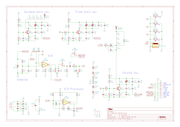
But, unfortunately, home made capacitors and shields is nothing I want. Edit4: After staring at ILYAs schematics for a while, I think there should be no problem to swapping out his oscillators for a pot-trimmed variant, instead of custom-capacitor trimming. The only thing that is needed is the correct levels in the signal path to the good ol' CD4520. Right? But only for the pitch oscillator. Duh!

Posted: 11/17/2019 3:17:13 AM
dewster

From: Northern NJ, USA

Joined: 2/17/2012

"But, unfortunately, home made capacitors and shields is nothing I want."  - CharmQuark

I know where you're coming from.  The Thierrymin uses a C trimmer rather than variable inductors, and I have no direct experience as to the stability, but I would bet there are some Etherwaves out there that went out of tune after being bonked around due to the inductor tuning slugs moving a bit.  IIRC Theremin himself used home brew caps for tuning some of his creations.  If the pitch side has a series "EQ" inductor I believe the proper place for such a trimmer is right at the antenna, where it can directly compensate for environmental C.  I think I'd rather roll my own caps as ILYA has done than roll my own variable inductors.  I do make my own fixed coils - it's easier than you probably think, and they work much better than anything you can buy.  But once you start winding coils you're in too deep! ;-)

One way to tune is by adjusting the antenna intrinsic C, a telescoping antenna can work here.  FredM used a threaded rod for the pitch antenna to give fine adjustment.  Moog used a dip in the wire going to the antenna over a piece of grounded foil to fine tune the pitch side in the Etherwave.  Millions of ways here, and it really helps that the other side of the tuning cap is ground.

Another design you might look into is the Burns: [LINK].  I believe it's RC and I have no experience there either.

Posted: 11/17/2019 5:51:33 AM
CharmQuark

From: Sweden

Joined: 11/14/2019

@oldtemecula, haha, I just did exactly that, tracing the rails on your board. Problem is, I'm talking about the schematics and the designators is not the same, so this is probably just too undocumented (or rather, confusingly documented). But, as you have proven the design I really think you should document it, it need to be saved for the future. Disk crashes suck, I once lost all my electronic cad drawings of ~20 years due to me being an idiot and backing up the wrong stuff. Not only schematics and PCBs, but also all those components I had made in various cad programs, the symbols and footprints, their link to datasheets, the order number for different parts-dealers, all BOMs, etc, etc, etc. It was horrible! I have a lot of PCBs I etched but never mounted components on (I if etch a board I typically etch a bunch, and when I need another gadget, I just take a new board and mount components. But that requires silk screen and bill of materials, which were lost. 

@dewster: well, once, I did my own coils and capacitors, but I simply don't want to rely on them and it is harder to share a project. I hate those project in general when you find a sensible and good construction, only to have a strange unsourcable or home made component as a show stopper.

I looked at the Thierrymin, but what I understand it's only a pitch control one. I will check out the Burns one, but now I have switched to investigate the ILYA design more closely. The two pitch oscillators can be exchanged to just about whatever as the design is waveform-agnostic so to speak. But the variable pitch one of course need to be sensible to an antenna. So I'm trying to see if the "wine box" colpitt oscillators do scale up in frequency while keeping sensibility. As for the volume antenna I thinking of keeping the variable cap, but as a off-the-self one and hoping that it only is needed during setup, as the volume level can be controlled with other means. Maybe I'm missing something, but I can't see that the "volume tuning" cap has to be connected to a front panel knob.

Posted: 11/17/2019 7:57:56 AM
CharmQuark

From: Sweden

Joined: 11/14/2019

Now I  have briefly looked into the Burns theremin. Well, its simple alright. Three sweet inverters left unused. The design almost whispers that it want volume control added. I think I need to start to build prototypes of selected parts of three different theremins now, to be able to choose path here. Already built the variable pitch oscillator from the "Wine Box Theremin" to check sensitivity at higher frequencies. No good result yet. I'm sitting in a noisy environment, in a flat with computers and several other things that has SMPTs, CPUs and what not. Need to plan for some more serious experiments with a little more control over the environment (incidentally, 50 Hz has *not* been a problem. The problem is the sensitivity of the antenna, which is way to low. On reason may be the proximity to metals here.

Posted: 11/17/2019 1:35:29 PM
ILYA

From: Theremin Motherland

Joined: 11/13/2005


"Millions of ways here" - dewster


In the next generation of "Paradox" I'm happy with DIY variable inductors:

0.53 mH for "pitch" (1500 kHz)
and 3 mH for "volume" (750 kHz)

Posted: 11/17/2019 4:04:02 PM
CharmQuark

From: Sweden

Joined: 11/14/2019

They are truly beautiful inductors, ILYA! Do you have a new revision of the schematic? What do you think about changing the oscillator topography? I'm thinking that any oscillator will do because of the signal path only going into digital clock inputs. Or do you have any suggestion for the volume antenna, how to make it without the custom trimmer capacitor (or L3 for that matter)? I hope you don't take it the wrong way, I'm *not* criticizing your design or choice of components. I understand the pride and craftsmanship in making own components, but I just feel I don't have the time or tooling to do so. I'm not naively think I can do anything better, I just want to do it more simple (if I were to build this in the end, I shall make an effort to try and source an К564ИЕ10 for fun. I already have a lot of Russian/old Soviet part from eBay, just because they are exotic here in the West).   

You must be logged in to post a reply. Please log in or register for a new account.