


Moog thinks I have a hardware issue and gave me an RMA for service. Sent the Claravox to them today.
Actual information on Claravox

Posted: 8/17/2021 10:33:20 PM
Hope this gets resolved to your satisfaction johnthom. Just curious, who's paying the shipping costs back and forth?
Moog is covering the shipping both ways via FedEx. They have been very engaged in resolving my issue which is reassuring and much appreciated.
Posted: 8/18/2021 8:35:25 AM

I am happy to report that Claravox #0039 finally arrived at its new home in Southern Bohemia (ordered late October 2020).
I am not so happy to report it seems to have the same issues on the volume side that others have noticed. Most of the time, it simply does not emit any sound except some crackles and pops when touching the volume antenna. Sometimes it can be persuaded to behave normally when I put the volume antenna reverse (open loop facing backwards). The pitch antenna arm has a snug fit, but the volume antenna is very wobbly. I wouldn't be surprised if it just has very bad or intermittent contact.
Unfortunately I am very busy in my day job right now so I can't really play around with it.
Posted: 8/18/2021 9:36:48 PM
I wonder if this is some sort of diagnostic code that kicks in when there is a situation (determined inexactly beforehand) that is outside of the normal operating parameters. Or maybe a corner case they didn't anticipate in the software (bug). Or ESD damaging the volume oscillator. It's too bad they didn't use the months of supply chain delay to better wring out wrinkles in the design. Then again, Theremins are a really tough biz, likely one of the very toughest, with a thousand ways to die. You might as well put a "Kick Me!" sign on your back. ;-)
Posted: 8/18/2021 10:29:14 PM

Most of the time, it simply does not emit any sound except some crackles and pops when touching the volume antenna.
I'm curious what you will hear when amplifying the apparent silence.
There's a faint signal on the main output of my Claravox #40, at approximately 1/100th of the full line level.

I contacted Moog on Monday morning but haven't heard back from them yet. Nevertheless I'm confident we will all have functional theremins in the end.

Posted: 8/21/2021 4:46:14 PM
DiggyDog posted a Moog link to some pix regarding the Claravox volume issue (much thanks DiggyDog!):
I made a TW album with the two relevant pix:
http://www.thereminworld.com/album/claravox-pictures/17463
And I edited one to yak about it some:
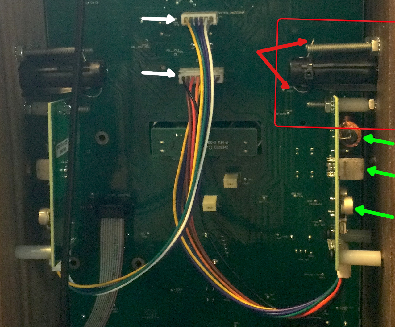
The top white arrow is the connector for the pitch antenna board, below it is the volume antenna board connector. It's rather counterintuitive that the volume has more wires than the pitch (8 wires vs. 6)? The antenna boards look the same in terms of physical mounting, if so, one could presumably simply swap their locations to make a lefty unit?
The red arrows point to what I'm guessing is some sort of unused spring connector at the end of a plastic guide tube which has an unused solder lug at the top (you can see this better in the other picture). From the instructions, they apparently opted to use the lower screw and star washer to make this connection, instead of the spring connector. A better practice IMO would be to insulate the antennas from the wood, which they seem to have abandoned here.
The green arrows point to various components on the volume antenna board. At top is an RF choke, at middle an IF type adjustable can inductor with access through the brass eyelet - these are a strong indication that the oscillator is of the EQ type like on the Etherwave, which uses the series choke to help linearize the near field, and boost the antenna voltage swing. The bottom arrow points to what appears to be a trim potentiometer? If the boards are symmetric then there are two of them. Perhaps this is what needs to be trimmed at the factory / repair shop.
The bottom nylon spacer on the volume board looks like it has a gap between it and the cabinet wall. There are other IDC ribbon cables in there, so I wonder why they didn't use those to connect up the antenna boards, the inter wire capacitance would be better controlled. I also might try to keep those two cable assemblies physically apart from each other.

Posted: 8/21/2021 9:35:55 PM
"To my eye this looks like a handwound coil. Am I very wrong?" - bendra
I'm pretty sure it's a commercial RF choke, like those in the EW. They're sorta scramble-wound, but there's a method to their madness.
Hey, can I persuade you to crack yours open and take some more detailed pix of the guts? I'm most interested in the oscillator boards.
You must be logged in to post a reply. Please log in or register for a new account.