LC Tank / Linearizing Coil Excel Simulation

Posted: 2/22/2013 12:27:35 PM
RS Theremin

From: 60 mi. N of San Diego CA

Joined: 2/15/2005

Hi there,

Your analysis is valid but If someone mostly writes volumes in a manner that only two people understand, what value is that to the masses? When someone is non-technical and I tell them amperage and voltage can be viewed as water flow in a hose that is metaphoric. When I tell them current flow goes in the direction of the arrows on a schematic and yet electrons move 180 degrees in the opposite direction a few will scratch their head as if I am all wet and argue the hose was not straight.

If I asked a Thereminist which way his arm is moving if I say push the audio higher in frequency I think they would know.  A few would miss the point and ask which side of Null are you on which is a valid question.

I never said anything about audio phase shift; you added that to weaken my waffle.

I did say I stated this incorrectly. "the L1 and L2 oscillators are 180 degrees out of phase" – RS

I leave the thread now as I just wanted to give my observations which were removed from my own webpage to cut down on waffle for better signal to noise for the masses.

In all honesty I do appreciate your feedback which is how I learn, problem is being older, it becomes more difficult to retain newly gained knowledge. (-:

Christopher

Edit: I forgot to mention that when using the spring coil antenna with series inline LC tuning between the parallel Hartley oscillator, the Hartley got upset if the ferrite rod used for antenna tuning was less than 6" away from the oscillator air core coil. It needed its space.

Posted: 2/22/2013 4:04:54 PM
dewster

From: Northern NJ, USA

Joined: 2/17/2012

Today I was wondering how the Glasgow antenna capacitance calculation (not the hand calculation) instantiated in my spreadsheet might jibe with measurements taken with my newish LC meter.  This LC meter works I believe by resonating a known internal C|L with the external L|C under test, making it something like a tiny Theremin.  The readout goes to 0.01pF, if it had one more decimal place you could very likely use it to directly read hand capacitance at some distance.  As it is it can "see" my hand out to several feet with the last decimal place.

Anyway, I hooked one side of the LC meter to house ground, connected the other side to the empty UHF connector mounted in the AFE plastic box sitting on my wooden workbench, zeroed the meter, then put three separate antennas I had laying around in the connector.  All antennas 10mm diameter covered in black heatshrink.

length (mm)   Calc (pF)   Meas (pF)

250                  3.96           3.40

330                  4.84           4.21

450                  6.10           5.56

This little experiment is quite crude, but it seems the calculated results are consistent with the measured values, which gives me confidence in the Glasgow antenna capacitance calculation (and in my LC meter to measure anything like this).

What's interesting is the level of stray capacitance in the AFE when I hook the antenna to a series tank oscillator constructed on the internal AFE breadboard (with no EQ coil so the LC resonance point is easily calculated, L=50mH, C=10pF).  With no antenna, I'm reading a resonance of 165.7kHz, which corresponds to a stray capacitance of 8.5pF.  These plastic breadboards do tend to have a lot of stray capacitance, probably not the best thing to be building Theremin circuits on.  [EDIT] Disconnecting the UHF connector from the breadboard gives 170.2kHz resonance, or 7.5pF stray capacitance.  So the UHF connector and wire contributes ~1pF, the breadboard ~7.5pF.  Fascinating what turns up with this kind of capacitance inventory.

Here is the oscillator I used (and intend to use again to measure hand capacitance):

50mH | 10pF tank, 10pf | 470pf forms a capacitive voltage divider, knocking the ~130V p-p at the antenna down to 2.7V p-p, the following inverter with feedback biases the divider to ~VCC/2 and squares it up some, output looped back to drive the tank inductor via 1k | 2000pF which gives an additional 90 degree phase lag (-90 @ LC, -180 @ inverter, -90 @ RC = -360 = oscillaton) and limits the drive current (which limits the tank & antenna voltages; the C also helps attenuate higher harmonics).  Buffer at output to unload and further square things up.  With a 9V battery supply it draws 3.7mA, which includes 3.3V regulator dissipation, so inductor / IC heating shouldn't be a problem. 

[EDIT] Not sure I'd recommend this oscillator for analog Theremin designs (though I have in the past!) as I've seen it fail to start up a couple of times.  Though you can get a beautiful sine wave at the capacitive voltage divider, a square wave at the output of the second inverter, a rounded square at the output of the first inverter, and (depending on C) a lopsided sine / RC charge-discharge type waveform at the RCL feed point.  Another interesting thing is the current limiting R can be varied to give quite fine control over the resonance frequency (though of course there is some interaction with amplitude).

Posted: 2/22/2013 6:05:35 PM
FredM

From: Eastleigh, Hampshire, U.K. ................................... Fred Mundell. ................................... Electronics Engineer. (Primarily Analogue) .. CV Synths 1974-1980 .. Theremin developer 2007 to present .. soon to be Developing / Trading as WaveCrafter.com . ...................................

Joined: 12/7/2007

"which would be a 180 degree shift for the audio frequency" - Christopher

"I never said anything about audio phase shift; you added that to weaken my waffle." - Christopher"

I am sorry - You are right, you never used the word "phase". This was an error on my part - not intended to weaken your argument.. When I see "degrees" and "shift" I think "phase" - but you never said phase, and obviously you never meant phase..

Fred.

Posted: 2/23/2013 5:55:48 AM
FredM

From: Eastleigh, Hampshire, U.K. ................................... Fred Mundell. ................................... Electronics Engineer. (Primarily Analogue) .. CV Synths 1974-1980 .. Theremin developer 2007 to present .. soon to be Developing / Trading as WaveCrafter.com . ...................................

Joined: 12/7/2007

I have just run some more tests on the Lev oscillator..

Sadly, when actually measuring hand distance vs frequency, I am not seeing anything exceptional happening with regard to linearity..

This contradicts my earlier experimental results - but this time I was only using a single oscillator without mixer of any kind on the board .. I ran this test as I am (or was) about to design a PCB, and was planning to play with the orientation of the inductors to determine the best positions / orientations for these before started designing the board. 

I started with the VFO in isolation, just to determine a "baseline" I could compare against constructions containing the reference oscillator and coupling influences - In prior experiments, there was no obvious coupling mechanism (the oscillators were buffered prior to mixing, and the supplies well decoupled) but I believed I was getting exceptional linearity.

I will be going back to my earlier boards to see whats happenning - I suspect that magnetic coupling between the hand-wound inductors may have been more significant than I had realised... Alas, I removed these inductors and cannot be sure of getting them back exactly as they were before! :-(

But, for now at least, I have doubts regarding whether the Lev oscillator topology really does what I had thought it did.. Quite a bummer!

I dont have the time right now to look into this with the depth required (I have other paying work to complete) and until I get to the bottom of it, I wont be doing the PCB - So am probably looking at a delay of about another month before the Lev Clone os on PCB... I will still proceed even if its not as good as id hoped, because its still ok.... And perhaps it will be great if I can duplicate the mechanism which appeared to give good results, repeatably and reliably.

If there is no big advantage in the Lev oscillator, its probably not worth using it - the extra complexity of the coils required will add substantially to the cost.. The only reason to use it would then be for "marketing" purposes only.. "Genuine Lev Oscillator".. (LOL) .. So I will follow this through until I am sure one way or the other, and may end up dropping the Lev oscillator altogether.

Fred. 


Posted: 2/23/2013 10:01:08 PM
dewster

From: Northern NJ, USA

Joined: 2/17/2012

"I will be going back to my earlier boards to see whats happenning - I suspect that magnetic coupling between the hand-wound inductors may have been more significant than I had realised..."  - FredM

(Spitballing:) Perhaps this is why that transformer is placed within the RCA EQ coil?

"But, for now at least, I have doubts regarding whether the Lev oscillator topology really does what I had thought it did.. Quite a bummer!"

My sincere condolences.  Always disappointing when expectations aren't met by a circuit, doubly so for that special one.

Posted: 2/23/2013 10:10:17 PM
dewster

From: Northern NJ, USA

Joined: 2/17/2012

Yesterday I collected some hand capacitance data for three different length antennas.  If my data is any good the equation for hand capacitance in that Glasgow paper is underestimating mid and particularly near field capacitance by quite a bit.  Seems like a lot of hand waving in that section of the paper so I've never really trusted it.  Spent the day buried in physics texts and pawing the web trying to get a handle on the situation - no luck so far.

Posted: 2/24/2013 7:25:06 AM
FredM

From: Eastleigh, Hampshire, U.K. ................................... Fred Mundell. ................................... Electronics Engineer. (Primarily Analogue) .. CV Synths 1974-1980 .. Theremin developer 2007 to present .. soon to be Developing / Trading as WaveCrafter.com . ...................................

Joined: 12/7/2007

" that Glasgow paper is underestimating mid and particularly near field capacitance by quite a bit.  Seems like a lot of hand waving in that section of the paper so I've never really trusted it.  Spent the day buried in physics texts and pawing the web trying to get a handle on the situation - no luck so far." - Dewster

Yes - I have not got results from the Glasgow maths which I have been able to see in practice.. I have not been able to trust them.. But Dont have the maths skills to even guess about where the problem/s are, not to be able to make sense of any other stuff I have found.

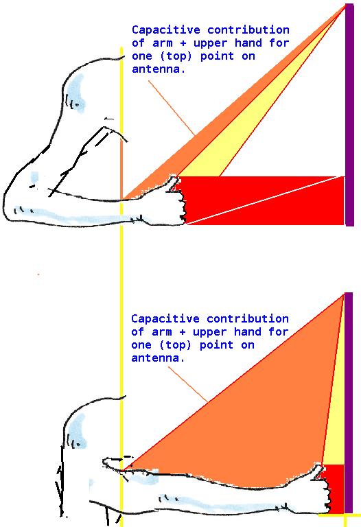
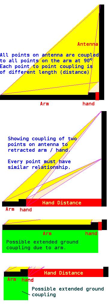
I strongly suspect that "underestimating mid and particularly near field capacitance " is due to angular coupling to the arm not being factored into the calculations - I am sure that this gives an additional capacitance "curve" which must be added - and it has maximum value closest to the antenna and drops to 0 when the arm is not extended.. I expect the curve will be something like a sine multiplied by inverse square of the distance.. or some similar geometric relationship based on arm and antenna length. I suspect that the deviation from the Glasgow sums will reduce as the antenna length is reduced. (as in, I suspect that length, and the lack of computing this WRT the arm, causes the error - and that if length is reduced such that coupling to the hand can only happen  purely on the X axis, the hand alone will be "seen" and there will be no additional arm capacitance to screw things up.. but such an antenna would probably need a length of perhaps 11cm, need to be perhaps 5cm diameter, and be more like a plate sensor)

Back before your spreadsheet I used a simple spreadsheet I devised which based hand capacitance on simple capacitive plate sums - I took the antenna diameter as the width of one plate, gave the hand "plate" the same "width" multiplied by a "fiddle factor" (usually 1.5) and gave both "plates" a length of somewhere like 10cm.. I summed both areas, divided this sum by 2, and let each plate be equal to this area.. Then computed hand capacitance for these plates seperated by distance, and added an antenna "background" capacitance constant which I just guessed at or was based on measurement.

The above was, like the Glasgow calculations, obviously innacurate - but it was easier to alter the fiddle factors to get what one wanted to see ;-) LOL.

What I really want is something like the above but where I can compute angular capacitive components to account for the arm - because I believe this is likely to be highly significant.. The length of the antenna, for example, if one is only calculation hand capacitance "directly in line" has no influence (provided it is linger than the hand on the vertical axis) other than to increase background capacitance - and this is obviously absurd.. I believe that for a correctly modelled antenna, the length will prove to be highly significant for linearity.

I think (but have not proved this, although experiments incline me to thinking there is truth in it) that longer thinner antenna give better linearity than short fat ones. I also think (unproven) that an antenna having the length of the null distance might be optimum for linearity.

But, for now, the calculations (however derived) at least give a "ball park" against which simulations can be run - they are certainly better than nothing.. And your spreadsheets have saved me a lot of time... One needs to define aproximate component values in order to even start playing with prototypes, and these calculations are still better than guessing. I think the truth, when it comes to capacitive sensing of such tiny changes over such large distances, that one will never get perfect simulation - there are just too many complex variables.. It comes down, in the end, to hands on -

Even "hands on" one has problems actually verifying what one is seeing - the environment, the test methods, all sorts of things can make a big difference - As I keep discovering and forgetting! ;-(

The irritation is that I am sure, given the details in my next posting, a highly competent mathematician could derive a formula which could be put into spreadsheets and which would return far more accurate results for theremin application.

Fred.

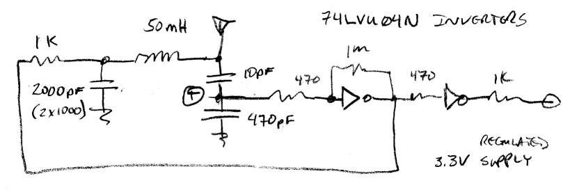
I am going back to voltage outputting AFE - With this I get a voltage proportional (although distorted) to distance.. A bit of analogue shaping and I can get this quite close to "Actual" (not musical) linear.. So I get 0 to 10V for distance from antenna to "null" point... This becomes a CV at 1V/Octave, can reduce it to whatever I want, say 0 to 4V for 4 octave coverage..

To go up an octave (register switching) just add 1V - one has complete control over range and register... This voltage will drive VCO's and VCF's etc... And I am able to control any "normal" heterodyning theremin using voltage control.. One can tack as many VC modules or theremins onto this CV as you want, independently tune them if you want, and end up with chording / polyphony.. You can add voltages from sequencers and get patterns controlled by the master AFE... Or one can simply have one theremin module and a register switch and have a true analogue heterodyning theremin with register switching..

Its complex, but gets rid of all the headaches - splitting the control mechanism from the sound engine (as you are doing with your digital implementation). Lev's design was brilliant in its simplicity, but this is the 21st century - I am quite sure that if Lev was designing a theremin today he would not do it the way he did in the 1930's ! And that his 21st century design would use present day technology and be far superior to the RCA or Claramin.

Perhaps I have been missing the reality - been seduced by the retro electronics facination (the dark side? LOL ;-).. The old technology has a place due to its simplicity, but is probably better suited to mid-range or low cost starter instruments and toys.. Adapting this technology to create modern pro instruments is probably silly.

Looking at Bob Moogs advanced theremins (particularly the EtherVox) all the "simplicity" is gone! - the boards are packed with loads of analogue and CMOS, Big SMD MCU's, Eproms, transistor arrays, multipliers - they are highly complex modern instruments - With the EtherVox about the only "retro" components are the large air coils and some stuff at the front-end... The number of trimmers in the E-Vox is frightening! Setting up one of these would give any technician nightmares! 

Fred.

Posted: 2/24/2013 9:14:11 AM
FredM

From: Eastleigh, Hampshire, U.K. ................................... Fred Mundell. ................................... Electronics Engineer. (Primarily Analogue) .. CV Synths 1974-1980 .. Theremin developer 2007 to present .. soon to be Developing / Trading as WaveCrafter.com . ...................................

Joined: 12/7/2007

This article is also available as a .pdf document at Element-14

Here are some diagrams showing my thoughts on the arms importance: (note the angle of 90 degrees is the arm / antenna angle, the coupling angles will vary from point to point (antenna - arm) from horizontal (hand - antenna) to almost 90 degrees (hand to top of antenna when hand is close to antenna) and everything between those.

These diagrams are obviously extremely simplistic - Another possible influence particularly if players grounding is poor, is that an extended arm will increase body coupling to ground.

The red "hand distance" is the largest variable capacitive component, and it is this (I believe) which is used in hand capacitance calculations.. It is my belief that IF this is true (that only this "red" area is computed, or only the hand is computed against the antenna length) the calculation of capacitance relevant to theremin linearity will be highly inaccurate, this inaccuracy increasing the closer the hand is to the antenna.

Fred.

(these diagrams do not look at players body couplings to antenna, but if the player is not moving their body, this should be a constant capacitance added to the antennas constant 'background' capacitance) - Also, for simplicity the hand is drawn oriented to the bottom of the antenna - it should not matter where the hand is on the vertical axis, as the lower and upper antenna sections and their couplings should equate to the same result.

The arms angle however will, I believe, alter both pitch and linearity.

Note also that the hand is also coupling to the whole antenna at all times, the direct horizontal coupling being most significant as the hand is closer to the antenna, but as distance is increased, the length of the antenna and the hands coupling to sections not directly in line with it become, I think, more significant.

Posted: 2/24/2013 4:38:58 PM
dewster

From: Northern NJ, USA

Joined: 2/17/2012

Hi Fred,

Nice pics!  When I took hand capacitance measurements the other day the cardboard "ruler" was sitting on my shoulder, and so my hand when closest to my body was at my shoulder, with my elbow down.  With my hand closest to the antenna my arm was straight out.  For all measurements my closed fist was held roughly vertical, and traveling on an imaginary line perpendicular to the midpoint of the antenna.

I'm trying to pick the brains of physics types over here, but the one friendly respondent is rather obtuse:

http://www.physicsforums.com/showthread.php?t=673974&referrerid=463651

"Its complex, but gets rid of all the headaches - splitting the control mechanism from the sound engine (as you are doing with your digital implementation)."

Some work up-front, but everything after that is much more straightforward and open-ended.  Spending a day in analog heterodyning land was enough for me.  Any more and I would have needed prescription meds!

"With the EtherVox about the only "retro" components are the large air coils and some stuff at the front-end... The number of trimmers in the E-Vox is frightening! Setting up one of these would give any technician nightmares!"

Fascinating stuff!  Are there pics of the E-Vox PWB anywhere? 

My goal, and I'm 100% certain it's attainable, is no trimmers of any sort anywhere, just constants held in a small SPI Flash or similar.

Posted: 2/24/2013 4:54:15 PM
FredM

From: Eastleigh, Hampshire, U.K. ................................... Fred Mundell. ................................... Electronics Engineer. (Primarily Analogue) .. CV Synths 1974-1980 .. Theremin developer 2007 to present .. soon to be Developing / Trading as WaveCrafter.com . ...................................

Joined: 12/7/2007

"Fascinating stuff!  Are there pics of the E-Vox PWB anywhere? " - Dewster

Theres a pile of high resolution photos here (check all Ethervox and Ethervox project "documents":

http://www.element14.com/community/groups/theremin-general-resources?view=documents

High enough res that with a bit of work, one could almost reverse engineer everything except the MIDI board!

8, 10 and 11 probably give best view of the boards - you probably need to download the images - the E-14 viewer sometimes does strange things, so dont trust what you see.. These are large files!

Fred.

I have just added a .zip to the documents - http://www.element14.com/community/docs/DOC-53115/l/ethervoxzip

Its BIG! Contains all the photos.

You must be logged in to post a reply. Please log in or register for a new account.