LC Tank / Linearizing Coil Excel Simulation

Posted: 2/24/2013 5:02:13 PM
FredM

From: Eastleigh, Hampshire, U.K. ................................... Fred Mundell. ................................... Electronics Engineer. (Primarily Analogue) .. CV Synths 1974-1980 .. Theremin developer 2007 to present .. soon to be Developing / Trading as WaveCrafter.com . ...................................

Joined: 12/7/2007

- Just had a look at your physics discussion.. ROFLMAO !  ;-)

I had similar "exchanges" there a long time ago - not about theremins, I hasten to add ;-) .. lets just say that I never got anything remotely usable or in any way approaching what I would deem practical or "reality"..

Theyr even madder than us here! ;-) LOL. I found the friendly respondents were obtuse and didnt really know a lot.. And those who perhaps did know were not friendly! (and were equally obtuse!).. But I suppose one can expect that if one questions E=MC2 or the 2nd Law .. ! ;-).. All the nutters see one as a "kindred spirit" and start spouting off about zero-point-energy and perpetual motion machines, and those grounded in solid science see any questions about these areas as either "baiting" or from some ignoramus.

Fred.

Posted: 2/25/2013 3:21:16 AM
dewster

From: Northern NJ, USA

Joined: 2/17/2012

"I have just added a .zip to the documents"  - FredM

Thanks for that!  Wow, lots of trimmers, lots going on in there in general.  A mostly digital Theremin could be simpler by an order of magnitude (here's hoping anyway, I'm not up to that level of construction).  Got any pix of the TVox Tour guts?

Another day lost to worthless capacitance calculations, maybe I'll email a PhD friend of mine.

The thing about Physics (and statistics, and many other engineering subject) is there is a unique trick to solving each problem, and if you don't know it you're SOL.  It doesn't help that the example problems they solve in textbooks are the easy ones (two charged plates without fringing, coaxial infinite cylinders, sphere in space, etc.).

Posted: 2/25/2013 9:27:15 AM
FredM

From: Eastleigh, Hampshire, U.K. ................................... Fred Mundell. ................................... Electronics Engineer. (Primarily Analogue) .. CV Synths 1974-1980 .. Theremin developer 2007 to present .. soon to be Developing / Trading as WaveCrafter.com . ...................................

Joined: 12/7/2007

"Got any pix of the TVox Tour guts?"

Yes, somewhere! ;-) .. A Japanese site did a deconstruction of one some years ago, with a few pictures (not a fraction as good as the E-Vox pics) - A friend was studying Japanese at the time (given it up now) and tried to translate for me, but it seemed that there was not much real technical detail. George Pavlov is not exactly forthcoming regarding whats inside it.. But there is no inductive equalizing, and when I asked him whether it used dynamic equalizing and told him my ideas on this he replied "No - I tried that at first, but it didnt work.." (I am probably paraphrasing severely).. He implied that the linearity was a function of "balancing"... (?) I have a strong feeling that the Tvox is not a "true" theremin - that it may be a CV based design.. or at least that its sound generation is seperated from its detection.

Anyway, I cannot find that Jap site again, but I do know I downloaded it - Tried finding this stuff but I think I upgraded my PC since then, so its probably in a pile of DVD's I backed everything up onto...  I have a catalog, so am sure I will find it when I really look for it.

" It doesn't help that the example problems they solve in textbooks are the easy ones (two charged plates without fringing, coaxial infinite cylinders, sphere in space, etc"

This is the bane of my life - simple examples, or "examples" where steps are omitted - particularly with maths - long example which I can follow, then suddenly some numbers or functions appear from nowhere and I am lost... I find this particularly with transpositions - formula re-arranged and I cannot see how this re-arrangement was derived.

"A mostly digital Theremin could be simpler by an order of magnitude (here's hoping anyway,"

It is horribly complex - And I dont think (not sure here - this is just a hunch) that any part of it is a true analogue heterodyning theremin.. Looking at the front end, I think that Ref and VFO are devided and logically mixed with an XOR (much like the E-Pro - except that the following VC processing probably enables far better analogue waveshape manipulation on the E-Vox) .. I suspect that the oscillators are tuned such that, prior to division, one gets a high difference frequency, and that this drives a pitch to voltage converter.

Having a CV allows the logic level difference (which is scaled by the register switch which changes the division) to be processed by voltage controlled filters etc - perhaps even VC waveshaping .. And the CV is digitised for MIDI O/P.

Then there is a full analogue VC Synth with VCO, VCF,VCA, which mimmics the "theremin" voice to allow playback of MIDI recieved data.

BUT - The above is almost pure speculation - I did start to get into the E-Vox, but located the problem too quickly, advised the customer, and they repaired it themselves! - So I never had a chance to fully examine the machine.

I think the complexity is more to do with the multi-functional nature of this beast.. One could mop up all the logic with a small CPLD, and if one rationalised on one topology rather than incorporating several, could simplify (eliminate) at least 50% of the analogue stuff.. Get rid of MIDI and one could make the whole thing a lot simpler.

But EVERYTHING I say above is PURE SPECULATION.

Fred.

Posted: 2/25/2013 11:44:10 AM
FredM

From: Eastleigh, Hampshire, U.K. ................................... Fred Mundell. ................................... Electronics Engineer. (Primarily Analogue) .. CV Synths 1974-1980 .. Theremin developer 2007 to present .. soon to be Developing / Trading as WaveCrafter.com . ...................................

Joined: 12/7/2007

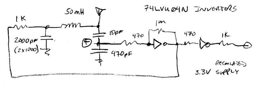
Just been looking at this circuit and it is really interesting - I can, however, see that it could be inclined to stall.. Needs a "kick start" mechanism (I have used a monostable with time-out set to a few cycles, so that if the oscillator stalls a pulse is generated which kicks the oscillator back into action - easily implemented with a spare inverter or two..)

The large inductor is my main dislike for circuits of this type - If one is going to put a big inductor in, one wants it to do something more than just be a tank L - As I see it, there is no mechanism for improving linearity conferred by this inductor..

But as a front-end for a digital system I can see this oscillator has some advantages - whether free-running or driven.

Fred.

Posted: 2/25/2013 2:50:31 PM
dewster

From: Northern NJ, USA

Joined: 2/17/2012

"Just been looking at this circuit and it is really interesting - I can, however, see that it could be inclined to stall.. Needs a "kick start" mechanism (I have used a monostable with time-out set to a few cycles, so that if the oscillator stalls a pulse is generated which kicks the oscillator back into action - easily implemented with a spare inverter or two..)" - FredM

Interesting use of a monostable! 

I've only seen this oscillator fail to start when I was measuring the supply current - the DMM series resistance likely gives it too soft a start so it is deprived of the kick it needs for the tank to ring.  The RC 90 degree lag can make the antenna voltage dip when my hand is very near or touching the pitch antenna, but I haven't seen it stall once started (yet).

The use of an FPGA in the loop would fix the startup issue as the driving NCO would be set to start somewhere around resonance so no initial kick would be needed, and the 'T' pickoff point monitored directly for 90 degree lag.  In this mode of operation the tank is more of a low pass filter.

"The large inductor is my main dislike for circuits of this type - If one is going to put a big inductor in, one wants it to do something more than just be a tank L - As I see it, there is no mechanism for improving linearity conferred by this inductor.."

Here I'm specifically not using EQ in order to keep the backward calculation from the resonance frequency simple for capacitance measurement, where the presence of EQ would confound things.  The inductor is large mainly because I just happened to have some quality Bournes 50mH laying around (that and the large tank inductance keeps the drive current low for hopefully lower thermal drift).  For digital Theremin use I'd probably go 5 to 10mH for both tank and EQ but the currents would be somewhat higher.  For this circuit EQ definitely makes it more sensitive - I haven't seen EQ alter linearity but I haven't done exhaustive testing along those lines either -  EQ | hand capacitance interaction with this tank seems simpler than for the parallel tank in simulation.

The "capless" reference design seems to have fairly low and fairly constant current needs regardless of operating point, which is super interesting (to me anyway).  Hope it pans out.

Posted: 2/25/2013 8:23:20 PM
Thierry

From: Colmar, France

Joined: 12/31/2007

Just a short info: I'm not (yet) completely through my tVox tour theremin, but I can already tell for sure that it is a true heterodyning instrument and that the mixer output goes through a wave shaping circuit before the VCA comes in. There is no VCF as I thought during years, and no pitch CV is flying around... 

Interesting fact: There is a hidden potentiometer which is accessible when you pull the pitch knob off. It allows to adjust slightly the coupling between the fixed and the variable pitch osc and thus to modify the tone spacing in the lowest register.

Posted: 2/25/2013 11:56:53 PM
dewster

From: Northern NJ, USA

Joined: 2/17/2012

New version up:

http://www.mediafire.com/?vzb0w79tq5xe651

- Revision History -
2013-02-25 : v8
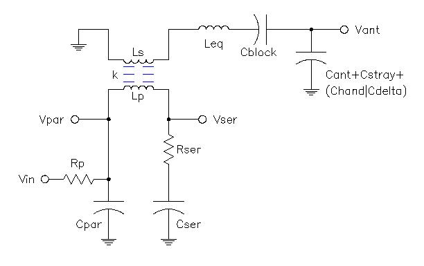
> Updated Theremin circuit to make Rser in series with Cser.
> Ditched Glasgow mutual capacitance formula, now using modified co-planar rectangular plate formula.
> Added "Antenna & Hand Data" worksheet with measured capacitance for three different antennas & new formula.
> Monkeyed with phase criterion and search method in Linearity VB, sim is somewhat faster and more accurate now.

The new hand capacitance formula matches my measured data much better than the Glasgow paper formula.  But the curves it gives, particularly near the antenna, seem to have broken my proposed linearization method!

Posted: 2/26/2013 6:11:00 AM
FredM

From: Eastleigh, Hampshire, U.K. ................................... Fred Mundell. ................................... Electronics Engineer. (Primarily Analogue) .. CV Synths 1974-1980 .. Theremin developer 2007 to present .. soon to be Developing / Trading as WaveCrafter.com . ...................................

Joined: 12/7/2007

"The new hand capacitance formula matches my measured data much better than the Glasgow paper formula.  But the curves it gives, particularly near the antenna, seem to have broken my proposed linearization method!" - Dewster

My condolances! I hope this deviation is not too severe..

I look forward to playing with the new spreadsheet.. I am primarily using your spreadsheet for quickly deriving ball-park capacitances to feed into my simulator (I do wish there was a way to automate this, but the simulation SW has no means of importing this data) .. I start by running simulation on your spreadsheet, then running real circuit simulations using capacitances at distances spaced 10cm apart, and comparing the results - this also allows me to examine the effects of coupling.

I will let you know what I find.

" but I can already tell for sure that it is a true heterodyning instrument and that the mixer output goes through a wave shaping circuit before the VCA comes in. There is no VCF as I thought during years, and no pitch CV is flying around... " - Thierry

Thanks for that, Thierry.. I am now even more puzzled about the Tvox.. Is the linearity primarily down to the "crafting" of the coupling I am starting to wonder..

I dont expect you to disclose any secrets - But back in the days before you launched your bass module, I was looking at bufferring the EW oscillators and adding a seperate coupling capacitor so as not to lose the coupling provided by C2 and C6..

From what I understand, your module buffers the oscillators and also improves bass end linearity.. So I wonder if this was achieved by providing a seperate coupling before the buffers, or whether uncoupling the oscillators improved the bass end linearity?

Fred.

Posted: 2/26/2013 7:11:07 AM
FredM

From: Eastleigh, Hampshire, U.K. ................................... Fred Mundell. ................................... Electronics Engineer. (Primarily Analogue) .. CV Synths 1974-1980 .. Theremin developer 2007 to present .. soon to be Developing / Trading as WaveCrafter.com . ...................................

Joined: 12/7/2007

I have just played with the capacitance section of your new spreadsheet -

Yes! the results from coplanar are much more like reality! Thank you, dewster!

Posted: 2/26/2013 4:02:04 PM
dewster

From: Northern NJ, USA

Joined: 2/17/2012

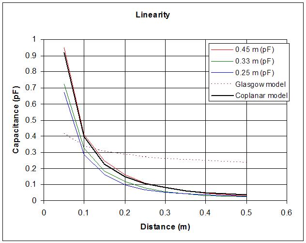
For those who don't use the spreadsheet, here's a view of the hand | antenna mutual capacitance vs distance data I took for three different length, 10mm diameter antennas.  (Hand data obtained with simple series tank oscillator without EQ coil, cardboard ruler affixed to the antenna, the other end resting on my shoulder.  My body seated in front of the antenna, my shoulders a constant 0.6m from the antenna center, hand in a fist, hand movement perpendicular to the midpoint of the antenna length, knuckles roughly parallel to the axis of the antenna.  Distance measured from center of antenna diameter to thumb tip.  A hand held frequency counter was used to measure and capture the data.):

The Glasgow model doesn't fit at all!  The coplanar model, with some prodding, fits pretty good but I'm not sure how accurate its predictive power is (e.g. changing the antenna diameter).  I believe the dimensional analysis works, but there are obvious factors it doesn't take into account.  Ah well, I scoured the texts available to me and the web as best I could, so until something better somehow pops up this is what I'm sticking to.  Obviously what one really wants here is a formula that fits the collected data exactly with no twiddling - a glorious mutual confirmation of both theory and data - but whatever.  The takeaway here is caveat emptor regarding yet one more thing in that Glasgow paper (which is a student paper so I probably shouldn't be too hard on them).  (BTW the best capacitance info seems to come from engineering metrology papers like this one.)

My proposed linearization scheme not working as a result of the new model isn't a big deal, it felt like a bit of a compromise to me anyway.

You must be logged in to post a reply. Please log in or register for a new account.