


hi dewster,
how you measure the coupling factors so accurately (or the ones are the estimated (calculated) values)?
"how you measure the coupling factors so accurately (or the ones are the estimated (calculated) values)?" - ILYA
The k=0.036 between the two separated coils is calculated with the program INCA: http://www.coe.ufrj.br/~acmq/programs/
I could measure it but I'm pretty sure the coupling is low because the measured series inductance of both together is only a bit larger than the sum of both measured individually.
The k=0.983 between the two transformer windings is measured via this method:
- Measure the primary inductance with the secondary open, this is Lp
- Measure the primary inductance with the secondary shorted, this is Lp_short.
- Measure the secondary inductance with the primary open, this is Ls
- Measure the secondary inductance with the primary shorted, this is Ls_short.
Then:
k = [ ( 1 - ( Lp_short / Lp ) ) * ( 1 - ( Ls_short / Ls ) ) ] ^ ( 1 / 4 )
Quicker but perhaps a bit less accurate:
k = sqrt [ ( 1 - ( Lp_short / Lp ) ]
OK, I just took the primary off, built up a ~2mm layer of Scotch Heavy Duty Packing tape on the secondary, and re-wound the primary back on top of this spacer. (I also worked on the winding jig a bit: added some wingnuts, a bigger crank disk, and a nylon crank handle.)
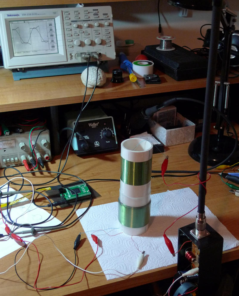
Stuck it back on the bench (see above). Primary / secondary interwinding capacitance is 172 pF or roughly 1/18 what it was previously. Primary / secondary coupling k = 0.889 which is what Inca calculates for this geometry.
What's weird is there are two resonance points, the expected one in phase with the drive at 680 kHz and an unexpected one 180 degrees out at 1 MHz. The 680 kHz resonance has roughly 4x higher voltage swing at the antenna and looks roughly 2x to 3x more sensitive to hand capacitance. (Scope trace above shows square drive to primary, sin-ish response across primary series resistance to ground, both in-phase at resonance).
Anyway, it's looking good! Much more in line with my spreadsheet sim. But I've got to find some other material to use for the 2mm primary / secondary spacer.

From: Eastleigh, Hampshire, U.K. ................................... Fred Mundell. ................................... Electronics Engineer. (Primarily Analogue) .. CV Synths 1974-1980 .. Theremin developer 2007 to present .. soon to be Developing / Trading as WaveCrafter.com . ...................................
Joined: 12/7/2007
Great looking coils! - Really interested in seeing how it all turns out. Must admit I am somewhat shocked by the large coupling capacitance (P to S).. but I suppose that if you simply wound one coil on top of the other without a low k barrier between them, the windings will fit closely into each other - probably effectively increasing the effective plate-plate area..
Your lab / coil / antenna setup is impressive and interesting (if a bit puzzling! ;-) .. In particular I wonder about the looped croc lead from the coil round the antenna, then to some connection point inside the antenna box.. I am guessing that this loop is of no significance and that the connection is made directly to the antenna via the socket.. but would be real interested if this is not the case - it looks like theres a bourns ferrite inductor in the box - I am presuming that this is old stuff and not used... (?)
Also really interested in the results from your capless design - If nothing else, it should give valuable data relating to real antenna+equaliser response, without the complications and possible ambiguities / errors that one may get when using a complex LC network of the 'conventional' theremin topology.
All good stuff IMO! I wish you well!
Fred.
From: Eastleigh, Hampshire, U.K. ................................... Fred Mundell. ................................... Electronics Engineer. (Primarily Analogue) .. CV Synths 1974-1980 .. Theremin developer 2007 to present .. soon to be Developing / Trading as WaveCrafter.com . ...................................
Joined: 12/7/2007
Hi Dewster ;-)
Once again, bith in the 'pub' at the same time! ;-)
Yeah - that new waveform looks a lot better!
WRT the resonance points.. I suspect you are getting a sort of "2nd harmonic" type "resonance" near 1MHz - as the frequency increases, I have found these "resonances" appearing at frequencies less than double the lower (probably "true") resonance point, I suspect its something to do with the coil capacitance - but 680kHz to 1MHz is the kind of 'step' in frequency I have seen (and been puzzled by) in several of my experiments.. I cannot say that I have observed a phase change, but then I wasnt bothered about the phase in what I was doing..
Might be worth cranking up the frequency and seeing if there is a pattern of resonance points.
Fred.
"Must admit I am somewhat shocked by the large coupling capacitance (P to S).. but I suppose that if you simply wound one coil on top of the other without a low k barrier between them, the windings will fit closely into each other - probably effectively increasing the effective plate-plate area.." - FredM
Originally I only had some battery pack type heatshrink between the secondary and primary. It measures 0.05mm thick so under those circumstances the high capacitance isn't too surprising. But I had to at least try it.
"...it looks like theres a bourns ferrite inductor in the box - I am presuming that this is old stuff and not used... (?)"
Good eye! Yes, old stuff and not used, the croc lead goes straight to the antenna. This is the AFE box, it currently has a simple series LC oscillator on the breadboard with no EQ coil - I used this a while back to measure hand / antenna capacitance in my spreadsheet.
I'll quantify the response soon. I'd have to look back in my notes, but my initial impression is that it is likely more sensitive than anything I've had on my bench to date, the phase change on the scope to my hand open/closed is quite obvious without zooming up.
"680kHz to 1MHz is the kind of 'step' in frequency I have seen (and been puzzled by) in several of my experiments.."
I believe (as you do) that these higher resonances are likely due to self-resonances of the coils (and so kind of a bad thing if not sufficiently far away from the operating resonance). I checked up to 2MHz (the limit of my function generator) but I don't see any others (though I'm sure my "rat's nest" setup isn't exactly clarifying things). Will spice this with the inter-winding capacitance included.
One could put an "electrostatic shield" between primary and secondary - a turn of aluminum tape with a slight gap between the ends so as not to form a shorted ring - and run this to ground. Wondering what the optimal spacing of this between primary and secondary would be...
When selecting the primary drive waveform I inadvertently hit the "triangle" button (instead of the square or sine) and the fit is very close to the output sine-ish wave (not surprising, but interesting to see). Made me wonder if I should make an 8 bit (or so, limited by resistor precision) R-2R ladder and drive it via the rectified MSBs of the NCO accumulator as it could potentially save me on dithering (which increases output timing resolution but is also a noise source that must be averaged out).
From: Eastleigh, Hampshire, U.K. ................................... Fred Mundell. ................................... Electronics Engineer. (Primarily Analogue) .. CV Synths 1974-1980 .. Theremin developer 2007 to present .. soon to be Developing / Trading as WaveCrafter.com . ...................................
Joined: 12/7/2007
"One could put an "electrostatic shield" between primary and secondary - a turn of aluminum tape with a slight gap between the ends so as not to form a shorted ring - and run this to ground. Wondering what the optimal spacing of this between primary and secondary would be..." - Dewster
This is one of the few things you have said that I really dont understand at all! ;-) - Sure, an "es shield" is doable.. but - Each winding would be strongly coupled to ground.. As I understand it, your drive signal is ground referenced, so the primary would become a tuned LC resonator.. As would the secondary..
Sounds like a really bad idea to me! ;-) ... Also, the gap would be subject to thermal expansion, so could possibly introduce thermal variations in the returned phase detection point.
IMO, if you want a reliable spacer between pri and sec, Mylar tape is probably a good choice.. I have used paper saturated in nail varnish, and I have also used PTFE plumbing tape (which is really easy to wrap over a coil - but has a problem that varnish doesnt stick to it, so you need to wind the coil tightly onto it - I like my coils to be rock solid and have no possibility of movement).
Paper soaked in varnish has worked well, but its messy!
Fred.
"Sure, an "es shield" is doable.. but - Each winding would be strongly coupled to ground.. As I understand it, your drive signal is ground referenced, so the primary would become a tuned LC resonator.. As would the secondary..
Sounds like a really bad idea to me! ;-) ... Also, the gap would be subject to thermal expansion, so could possibly introduce thermal variations in the returned phase detection point." - FredM
High quality audio transformers often employ ES shields (link). True that this could aggravate thermal expansion. Coils are such bundles of compromise.
True also that an ES shield would form a C to ground for both primary & secondary windings. But capacitive interaction is already happening between them, and they operate at a lower impedance than the EQ coil. The entire primary is oscillating ~2V p-p and this probably looks a lot like ground to the secondary which has one end grounded and the other end hooked to the EQ coil and swinging ~30V p-p. If I were to install an ES shield I think I would first try positioning it physically closer to the primary than secondary.
An ES shield would also help protect the drive and detection circuitry from ESD events at the antenna.
The drastically reduced harmonics of triangle drive would certainly make an ES shield less necessary, I'm going to pursue this angle.
Air-core is really exciting though - who'd think you could build high Q coils and tightly coupled transformers with such primitive supplies?
Placing my hand on the antenna box and holding one lead of a 1 pF capacitor in my finger tips and the other end very near but not touching the alligator clip, I see ~671 kHz. Touching the cap to the alligator clip gives ~650 kHz or roughly 3 %F/pF. My sim predicts 4.4 %F/pF for this antenna geometry which is surprisingly close given the crudeness of this measurement.
Putting this in perspective, the parallel tank EWS with its comparatively huge EQ coil can theoretically give ~4.5 if you tune it (tank LC vs EQ & antenna C) just right. My previous series tank designs were more in the neighborhood of ~3.5 and required no tuning. Going series capless seems as though it may give the best of both worlds, high sensitivity with no tuning. Plus likely good ESD isolation due to the tank transformer.
[EDIT] Nature may have handed me a gift horse, and it's unfortunately incumbent upon me to look it in the mouth. So I'm waiting for the other shoe to drop and blow it all up, which makes me highly averse to investigating it too thoroughly. :-)
Apropos of nothing, a Bob Moog video:
He says (in the first minute or so): "When I'm thinking about how to solve a particular problem, I can think about it for days and weeks and nothing will happen. And then, some day when I'm cutting the grass or I'm having a hamburger or I wake up in the middle of the night, the idea will be there. I think it would be egotistical of me to say I thought of it. What happened is I opened my mind up and the idea came through and into my head. These ideas, I don't have to dig up anything, sometimes I don't even have to be thinking about them, and there they are. It's something between discovering and witnessing."
I'm going to be a bit less New Age and a bit more egotistical than Bob M. and say that the huge amount of conscious time that one must give over to this sort of mental activity - even if it is ultimately solved in an unconscious way - allows one to say that they "did" it. Brains are weird but IMO you fully own yours as well any claim over what it may however unwittingly belch forth.
You must be logged in to post a reply. Please log in or register for a new account.
