Let's Design and Build a (mostly) Digital Theremin!

Posted: 8/17/2013 4:43:12 PM
dewster

From: Northern NJ, USA

Joined: 2/17/2012

The capacitance between the primary and secondary is really bugging me - this is supposed to be a "capless" design after all.  Yesterday I measured it more exactly as 108 pF, and was able to obtain similar results in LTspice using 1/2 of this capacitance from primary to secondary, which makes sense.  I also tried a makeshift auto-transformer configuration not utilizing the primary winding and was able to get seemingly decent results even though the two secondary coils aren't coupled well at all. 

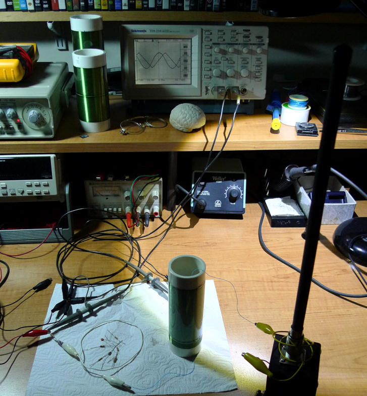
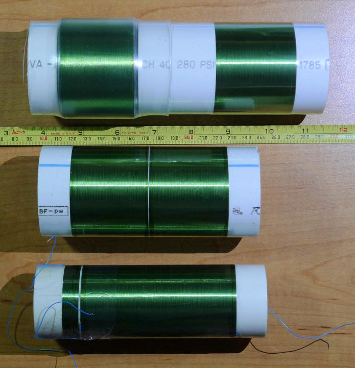
So today I wound a new single layer coil of double length (~100 mm) with a center tap.  On the bench I'm driving the center tap (50 ohm drive) with a triangle, one end of the coil is grounded through a 1k resistor, the other coil end is connected to the antenna.  Am seeing roughly the same amplitude sine across the 1k resistor as the driving amplitude triangle.  Sensitivity seems (very subjectively) good.  Coupling between the two sections measures ~0.2 which is what inca predicts.  Total inductance is 9 mH.

Phase at resonance (~800 kHz) is in-phase with the drive, which makes sense as the whole coil is resonating and requires the least amount of drive at resonance.  The main thing that bugs me about this setup is the low impedance center tap drive (bad for ESD back drive) - and I can't say I completely understand the feedback mechanism.  Wondering if I should just drive one end of the coil and have a small secondary coil for resonance detection.

[EDIT] I think I'm going at this backwards (or sideways?).  I should probably drive the coil from one end, the antenna with the other end, and use a secondary winding or tap to sense resonance.  Having significant power transfer between the windings is perhaps asking for it.

Posted: 8/19/2013 8:43:44 PM
dewster

From: Northern NJ, USA

Joined: 2/17/2012

"Her name is Agua Bella"  - RS Theremin

Thanks RS, but, as before, I'm not really sure what's going on with your designs, and you seem reluctant / unable to systematically explain them.  I do believe the operative Theremin field is purely one of capacitance - which is a form of energy transfer BTW - and it would require some pretty fantastic evidence to make me believe otherwise.

Posted: 8/20/2013 2:30:12 PM
dewster

From: Northern NJ, USA

Joined: 2/17/2012

"One thing that gets misunderstood is I have never said the pitch field response was not a capacitive effect, I only say there is more to it and this seems to upset those that only model"  - RS Theremin

You saying this doesn't upset me in any way, but I do disagree with the statement.

"The theremin has many characteristics that cannot be modeled..."

I also respectfully disagree with this.

"My latest antenna design is very real and it seems to me to use the environment and ground as the “plates” of a Leyden Jar using the salt water as an electrolytic. Tell me, how hard would it be to model this concept and then we might advance."

We are traveling two very different roads: mine is modeled and digital, yours is focused on exotic pitch antennae.  There doesn't seem to be much in common between the two approaches, and my plate is rather full at the moment.  Would you like to try an FPGA in one of your designs?

Posted: 8/20/2013 5:38:52 PM
RS Theremin

From: 60 mi. N of San Diego CA

Joined: 2/15/2005

> There doesn't seem to be much in common between the two approaches, and my plate is rather full at the moment.

I wish you success, this foggy old brain of mine misinterpreted what you meant by AFE.

Christopher

Posted: 8/20/2013 10:06:39 PM
dewster

From: Northern NJ, USA

Joined: 2/17/2012

"I wish you success, this foggy old brain of mine misinterpreted what you meant by AFE."  - RS Theremin

Thanks, I wish you success as well!  The AFE is under construction and may actually disappear at some point.

Posted: 8/20/2013 11:36:50 PM
dewster

From: Northern NJ, USA

Joined: 2/17/2012

Henceforth I shall quote any new RS Theremin posts in their entirety.  These disappearing posts of his make me look like I'm talking to myself (and I'm doing that too much in this thread already).

Got some 1.5" (as well as 3" and 4") PVC schedule 40 test caps today, will try winding some slimmer, longer coils in an attempt to reduce self capacitance.  The coil (and AFE topology) needs to go to bed and stay there.

Similarly, the Hive instruction set won't stay put - I'm strongly considering in-line relative (+/-16 bit) jumps as were suggested by Thomas over on comp.arch.fpga.

Posted: 8/22/2013 5:16:04 PM
dewster

From: Northern NJ, USA

Joined: 2/17/2012

NEW COIL / OSCILLATOR!

I believe I've finally found what I was looking for in terms of coil / oscillator topology.

Simulations in Inca indicate decent coupling (k=~0.4) between small single layer coils wound on the same former adjacent to each other (as opposed to one on top of the other).  This is advantageous because adjacent winding is much easier to do, and it also minimizes the capacitive coupling between the windings.

So this morning I wound a 6.181 mH coil on a piece of 1 1/2" schedule 40 PVC pipe, which is a ~100 mm width tight single layer winding of 34 AWG single coat copper wire - this is the primary winding.  At one end I wound next to it a tight single layer ~10 mm width of the same wire which measures 0.27 mH - this is the secondary winding.  I don't believe the length or inductance of the secondary is very critical as coupling falls off pretty quickly with distance.  I'm driving the primary with a triangle wave through 470 ohms, with the other end connected to a standard Theremin antenna.  The secondary is grounded on the side nearest the primary (to further reduce capacitive interaction) and the secondary current loop is completed through a 10k resistor.

I believe I was barking up the wrong tree in my previous attempts to stimulate a larger coil via a smaller one.  In this new arrangement the larger primary is stimulated directly, and the smaller secondary is used only for detection.  Phase diagrams from LTspice are very clear, and the actual circuit behaves better than anything I've seen thus far with good sensitivity and no secondary resonances (up to the upper 2 MHz frequency limit of my function generator).  The detection point is fairly low impedance, though significantly loading it reduces output swing at the antenna (in simulation).  The 10k sense load cleans up the otherwise somewhat ripply output, and gives a nice sine output with triangle input drive, with roughly 1:1 amplitudes (with 470 ohm drive).

From the scope picture above you can see what appears to be the sine output leading the triangle input by 90 degrees at resonance.  In actuality the output is lagging by 90 degrees with 180 inversion due to the coils being connected out of phase.  Quadrature is a good thing as it is very easy to detect and drive with a DPLL.

Resonance with this antenna (~10mm diameter, 250 mm length) is around 660 kHz.  The only resonant components are the primary winding and the antenna capacitance - there is no "tank" capacitance in this topology - so sensitivity (in terms of dFreq/dC) is maximized.  I believe the antenna end of the primary is almost completely decoupled from the drive end, but if necessary it could be further decoupled by breaking the primary into multiple winding groups with a bit of separation distance between each.  The decrease in overall coupling would necessitate more wire to reach the equivalent inductance.

I should also add that, due to the wide angle lens on my camera, the new coil on the bench looks very similar in size to the two older ones sitting next to the scope.  While the new coil is approximately the same height as the older coil nearest to the camera, the diameter is significantly smaller (43 mm vs 60 mm).  This is an attempt to lower the self-capacitance of the primary, and to get the "business end" or antenna end of the primary coil some distance away from the drive end.

Posted: 9/1/2013 4:28:25 PM
dewster

From: Northern NJ, USA

Joined: 2/17/2012

A better view of the coils I've been working with - progression through time from top to bottom:

The thin "battery pack" (PVC) heat shrink tubing seems to work really well at physically containing the windings and protecting them from scuffs and such, but I need to buy a smaller diameter if I continue to use 1 1/2" schedule 40 PVC, there is an obvious wrinkle visible here on the lowest, smallest diameter coil.  It doesn't take much heat to make it shrink, a hair dryer might work.  I kind of wish it were a bit thicker, and that it took a bit more heat to shrink it.  That's conventional (polyolefin) heat shrink on the left winding of the top coil, it's really not what I'm looking for as it takes a lot of heat to shrink it, and it feels a bit too pliable even after it is shrunk.

I'm currently using a couple of coats of clear nail polish only on the end 5mm width or so of the end windings to help anchor them while I solder on the wire wrap wire.  There's no indication of it, but I worry about the nail polish solvents maybe attacking the insulation / heat shrink over time.  Should I maybe be using some kind of quick dry lacquer instead?  Epoxy would likely be too messy.  Any advice from the coil winders out there would be much appreciated!

[EDIT] Sprayon EL600 looks like an interesting product.

Posted: 9/1/2013 7:18:51 PM
dewster

From: Northern NJ, USA

Joined: 2/17/2012

Spreadsheet Simulator v9

Here it is:

http://www.mediafire.com/download/8n88bg2kojdj5ve/Theremin_simulation_v9_2013-08-30.xls

This will hopefully be the last revision for a while.  The exercise has been very enlightening for me, but I feel like it's getting kind of mined out.  So unless a mysterious new oscillator topology needs investigating, or a new hand capacitance model pops out of the woodwork, I'm going to let it sit and concentrate on other aspects of Theremin design.

- Revision History -

2013-08-30 : v9
> Back to the transformerless two inductor circuit model which is simpler, easier to understand and use, and covers most of the design bases. 
> Anything more exotic than this should probably be Spiced.
> New "Tankless" reference design (phase detection is via a secondary transformer winding, not shown).
> Modified "Bode" worksheet phase detection so that it also works when Freq Start > Freq Stop (to detect highest resonance rather than lowest).
> "Linearity" worksheet now has similar phase detection as "Bode" worksheet (but it only detects the lowest resonance).
> "Linearization" worksheet is now a bit clearer in the way it operates.

Posted: 9/2/2013 6:27:27 PM
ILYA

From: Theremin Motherland

Joined: 11/13/2005

"Should I maybe be using some kind of quick dry lacquer instead?"

I use a drop of  "Chinese snot" (hot glue) which is applied by a soldering iron. Sometimes it looks not nice, but it is convenient at prototyping.

You must be logged in to post a reply. Please log in or register for a new account.