Let's Design and Build a (mostly) Digital Theremin!

Posted: 11/28/2013 8:35:29 PM
FredM

From: Eastleigh, Hampshire, U.K. ................................... Fred Mundell. ................................... Electronics Engineer. (Primarily Analogue) .. CV Synths 1974-1980 .. Theremin developer 2007 to present .. soon to be Developing / Trading as WaveCrafter.com . ...................................

Joined: 12/7/2007

"Since you are driving the antenna directly with a fixed frequency, you don't need any kind of feedback other than phase information to tune the tank L or C.  If you go tankless you can only change the L." - Dewster

Hi Dewster,

(I too, am  spit-balling without a net, there be crazy talk here):

I am feeling really slow today, just spent the last 1/2 (0.5 LOL) hour trying to explain fractions / decimals to my 8 year old daughter, and getting confused - My 9 year old son (who is absolutely brilliant with maths - calculates quite complex sums mentally far quicker than me - and also beats me at chess ) butted in and explained it all to us both, LOL ;-)..

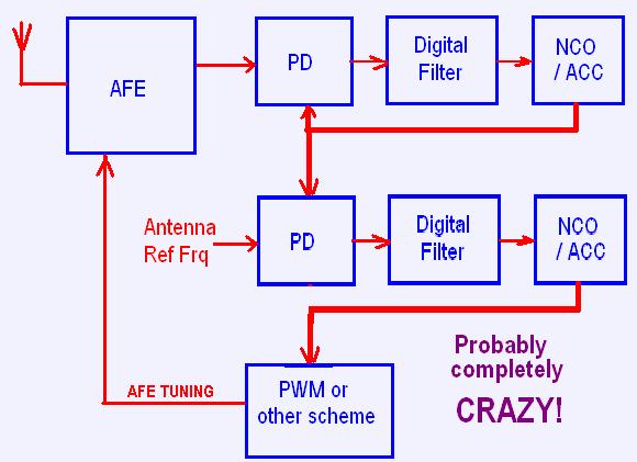
Ok - not really sure I understand what you are saying.. I think you are suggesting not having the oscillator configured as an oscillator, but have it as a resonator driven with a fixed frequency (MO), and using whatever tuning mechanism to keep this resonator tuned to the MO frequency - as in, as the resonator frequency tries to change when capacitance changes, the PD pulls it back to MO by retuning it (changing L or C). 

This does look like a sensible direct was to achieve what I want (an error voltage proportional to capacitance).. Often, however, one makes ones choices based on past expieriences - and I had great difficulty with this approach when I originally tried it on Epsilon (4 fixed frequency antennas).. I now know that I didnt know what I was doing back then ;-).. But the fear remains! - I switched to using a simple driven resonator and amplitude (AM) detection on the antenna - a scheme I still use for volume, driving this resonator from the reference oscillator or multiple thereof in a conventional theremin design.

The thing I really like about the oscillator scheme is that this design automatically 'locates' the resonant frequency - it sort of has two control loops, one being (if tuning wasnt automated) a free running oscillator at the resonant frequency, the other being the PD which tunes the resonator to the MO frequency - it just "feels" safer and easier to me for an analogue system to operate like this.. I can, however, see that for a digital system, driving the resonator with a fixed frequency and simply looking at the phase is probably easier... It may well be easier to do this in analogue as well - but having had the error voltage shoot off in the wrong direction, never to return, because something pushed the PD onto the wrong path, has kind of put me off this approach.

"It would be nice if you could change the L linearly, so as to use the error as an output.  I wonder if you could use high speed PWM to switch in / out a small section of winding in a tankless design?  Or variably saturate the 6300 with another winding?"

Those switching ideas are interesting - Really interesting - Not fond of using the 6300 as a saturable reactor though - they are a lot of hassle... Fine in a parallel topology where one can pass DC through the main winding without having to choke this, but too much hassle in a series config..

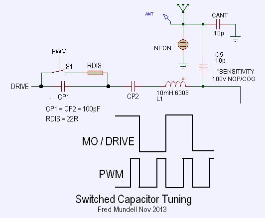
But the switching scheme - hmmm... I wonder if the PWM was at the same frequency as the MO (or perhaps twice this, so each 1/2 cycle got the same treatment)..

In fact, probably dont need to tap the inductor.. just have two series capacitors on the drive side, and switch between these - effectively altering the 'C' component of the total LC .. Just ran this crudely on the sim, and it looks awesome - adding almost any control range one wants (make the C's too small and output amplitude is impacted - but I got 10kHz tunability easily with sensible sized caps) * should just emphasise that this was extremely crude simulation which didnt implement the PWM - I just substituted capacitor values calculated as if I was PWM'ing.

Anyway - no more for tonight.. Ive spent far too much time and have a pile of legal letters I have been avoiding, but if I delay any longer could end up even deeper in brown sticky stuff!

Fred.

Posted: 11/29/2013 5:55:46 AM
FredM

From: Eastleigh, Hampshire, U.K. ................................... Fred Mundell. ................................... Electronics Engineer. (Primarily Analogue) .. CV Synths 1974-1980 .. Theremin developer 2007 to present .. soon to be Developing / Trading as WaveCrafter.com . ...................................

Joined: 12/7/2007

ok - cannot stay away from this - the solicitors or going to drag me down no matter what I do, may as well go down in the closest I can get to a "blaze of glory" LOL ;-)

Not yet fully simulated (need to implement the phase detector and have the oscillator locked, so I can generate a ramp at twice MO frequency, in order to generate analogue PWM) - But its looking good..

(First tried with C/O switch, but this failed abysmally due to capacitor holding charge from previous 1/2 cycle)

Probably only need CP1, just short CP2.. And could probably move CP1 to a more convienient point on the drive side.. I will probably use a MOSFET driver for the output - these parts are lovely - fast source / sink, 8 pin, drive enough to fry any small inductor, but the best feature is one can adjust the output drive voltage to taste from 4.5 to 18V.. Put CP1/ switch directly on the output of this, followed by the drive resistor...

I am thinking of doing linearity control by shaping the PWM ramp.. As in, keeping the whole loop 'closed' and not having a seperate shaping circuit... The tuning and span would then be simple gain / bias operations on the output from this loop.

(RDISH probably not needed - its just habit to put an R in series when shorting a C - but the 4066 switches own on resistance and the small C size probably makes this redundant)

Posted: 11/30/2013 9:26:24 PM
dewster

From: Northern NJ, USA

Joined: 2/17/2012

Interesting Fred.  It occurs to me (because your drawing looks something like this) that even in a tankless design you might be able to vary a largish C a little bit (via PWM) in series with the L, forming a C-L-C with the L swinging a little on the largish C side and swinging a lot on the antenna C side. 

Drive the largish C through an RC LPF with the cutoff set high enough to not substantially diminish amplitude or range, but low enough to kill a lot of the higher harmonics. 

Observe the whole thing through a secondary winding, compare it to post RC LPF phase.

A delay locked loop would work if 2x frequency PWM is sufficient (who knows?).

Posted: 12/1/2013 5:45:03 AM
FredM

From: Eastleigh, Hampshire, U.K. ................................... Fred Mundell. ................................... Electronics Engineer. (Primarily Analogue) .. CV Synths 1974-1980 .. Theremin developer 2007 to present .. soon to be Developing / Trading as WaveCrafter.com . ...................................

Joined: 12/7/2007

" It occurs to me (because your drawing looks something like this) that even in a tankless design you might be able to vary a largish C a little bit (via PWM) in series with the L, forming a C-L-C with the L swinging a little on the largish C side and swinging a lot on the antenna C side. " - Dewster

I must admit, I am perhaps a little confused over terminology here - "tankless" in particular..  I presume by this you mean that one is driving the antenna resonator directly from a fixed  frequency and using the phase data to derive capacitance - rather than the antenna resonator being a series resonant "tank" for an oscillator?

"A delay locked loop would work if 2x frequency PWM is sufficient (who knows?)."

I am "building" the complete simulation at the moment for this frequency/phase locked oscillator, using a 2*f PWM.. Initial simulations of individual bits look good - the L and antenna C seem to act as a good-enough filter so that the antenna-side signal returned to the gain stage input that no problems occur - and the antenna waveform is I think free enough of distortion to be acceptable (as in, its not going to radiate loads of harmonics - there is a little bit more distortion due to switching the drive-side tuning capacitor, but I think its ok.... If I can, I may go up to 4f, but might need to reduce the MO frequency to do this, particularly if implementing linearization through modification of the PWM ramp shape).

Stay tuned.. ;-)

*I will be creating a new thread to continue on - I am finding it a bother to trace the different links related to your oscillator and this discussion, so will put these in this new thread.

 http://www.thereminworld.com/Forums/T/29201/possibly-a-new-theremin-topology-and-links-to-related-background

Fred.


Posted: 12/1/2013 1:37:26 PM
dewster

From: Northern NJ, USA

Joined: 2/17/2012

Fred, I'll comment over on your new thread.

Posted: 12/5/2013 9:01:40 AM
FredM

From: Eastleigh, Hampshire, U.K. ................................... Fred Mundell. ................................... Electronics Engineer. (Primarily Analogue) .. CV Synths 1974-1980 .. Theremin developer 2007 to present .. soon to be Developing / Trading as WaveCrafter.com . ...................................

Joined: 12/7/2007

Hi Dewster

Your answer here:

"Yes.  The DPLL NCO kicks out a wave which is used to drive the series tank L.  The DPLL phase detector compares the phase of this to the output of a secondary winding on the series tank L, which is 90 degrees delayed at LC resonance.  The DPLL loop filter has a phase error integrator which is conveniently low pass filtered by the DPLL construct.  It's pretty much crying out to be used in a Theremin.  The whole thing is actually more of delay locked loop and could perhaps be implemented that way if one could get sufficient long-term error information (NCOs are handy here because they can be made arbitrarily accurate by simply increasing the bit width)."

causes me to feel incredibly stupid! - Now that I understand, its so bloody obvious (looking back over this thread) that I cannot see how I had entirely the wrong idea about what you were doing..

Real neat! And I can see how, by using this DPLL method, you can get extremely good resolution, fast tracking, LP filtering - all the things you have been saying.. My thinking was 'shaped' by analogue PLL operation - I was thinking in terms of actual "reference" frequency being generated in the FPGA - and thinkin in terms of having to generate this and the resolution problems this could incur... But using an accumulator and simply inc/dec of this to track the varying frequency/phase... Yeah!

And I can see why you worry a bit about running a volume DPLL simultaneously - it all makes sense! - Fact is, I never understood DPLL's ! - I have only ever used these really to multiply some constant frequency up to another - and used tools where one simply fed the multiplicand into a box and the DK did the rest..

Fred.

(I am pondering though, whether you could use phase comparator and accumulator in the same way, but instead of using the accumulator to drive the DPLL, you used it to drive a PWM or something like that to tune the AFE - that way you may be able [?] to have constant antenna frequency regardless of antenna size / capacitance, and still retain the advantages of your scheme.... Just pondering though... I dont think I understand the implications of the accumulator and filtering processes enough to know if this is a BS idea)

 One big problem I can see, which you mentioned before, is the issue of tuning the AFE - getting a high enough resolution from PWM or whatever could be a problem also.. Hmmm... Your direct method is certainly better - Oh well ;-( .. Was kind of hoping to drag yours into the constant frequency group, LOL, but it seems the next generation of theremins could still be variable frequency....  ;-)

Posted: 12/5/2013 6:34:34 PM
dewster

From: Northern NJ, USA

Joined: 2/17/2012

"Now that I understand, its so bloody obvious (looking back over this thread) that I cannot see how I had entirely the wrong idea about what you were doing.."  - FredM

Not your fault, I never ponied up block diagrams as you have for your ideas.  I keep meaning to do a short paper on where I am now with the digital Theremin but am swamped with various other things.  (Hive now has 8 stacks and so is somewhat larger (1.8k => 2.4k LEs; 20 => 24 BRAMs) but IMO is easier to program at the lowest level.  Am finishing up the re-verification and examples boot code, I also need to edit the design paper and update the simulator to reflect these changes.)

"I am pondering though, whether you could use phase comparator and accumulator in the same way, but instead of using the accumulator to drive the DPLL, you used it to drive a PWM or something like that to tune the AFE - that way you may be able [?] to have constant antenna frequency regardless of antenna size / capacitance, and still retain the advantages of your scheme...."

If PWM indeed works for tuning the tank (I haven't even simulated it) then what you are describing should work.  An analog implementation might (should?) also work.  The two XOR phase comparator inputs would be 1. the fixed frequency driving the tunable tank (post RC if there is one) and 2. the capacitive divider tap (or additional transformer winding).  LPF this and integrate the error to drive a VCO (standard PLL loop filter), the output of which would go to another XOR gate or similar to generate PWM based on phase difference.  You might be able to have the the XOR phase detector do double duty here, I haven't given it sufficient thought.

The DPLL (a PLL could also be used) approach is more direct and doesn't require tank tuning circuitry, but obviously gives a variable frequency at the antenna.

Posted: 12/5/2013 8:38:44 PM
FredM

From: Eastleigh, Hampshire, U.K. ................................... Fred Mundell. ................................... Electronics Engineer. (Primarily Analogue) .. CV Synths 1974-1980 .. Theremin developer 2007 to present .. soon to be Developing / Trading as WaveCrafter.com . ...................................

Joined: 12/7/2007

"If PWM indeed works for tuning the tank (I haven't even simulated it) then what you are describing should work. " - Dewster

I dont think it will for a digitally generated PWM -

My crude simulations have had a complete PWM cycle within each 1/2 cycle of the MO (as in PWM frequency is 2*MO) - doing it at MO caused waveform wierdness and screwed up stability of the loop.

I am simulating generating the PWM by having a shaped ramp (the shape / curve of this ramp is where I plan to impement linearity correction) going to a comparator, the other input of which is driven from the PD filter (and the PD/Filter is quite unconventional) -

In the past I have found that using analogue comparators, even though their speed is not as high as what one can accurately generate with a PWM generated digitally, tend to give far better analogue resolution - the comparator output jitters equally about the mean value (due to noise) and this jitter produces what behaves like a higher resolution PWM output than what one might expect.

With a digital PWM, and a fast (MO*2) PWM output frequency, the clock rate required to get anything usable in terms of resolution is extremely high if one is to avoid zipper effect I think .. with a MO of 125kHz, and a tuning step resolution of 4096 steps over the playing field (which I think is the lowest possible acceptable resolution , if one is spanning 3 octaves) one requires a PWM clock of 1024MHz - and thats without any elbow room for antenna capacitance retuning..

I must admit that on closely calculating what resolution relates to in terms of the PWM in the tuning scheme I devised (based on your original inductor switching suggestion - which I probably completely misunderstood ;-) I am wondering if this scheme will actually work in practice.. There is no way that the comparators switching speed will get anywhere close to whats required - and it will all come down to noise and the integration of this, and the effect of possible cumulative errors.. All stuff where the simulator is likely to give better results than real-life will. 

I am still of the opinion that it will work - but this opinion is based on having similar schemes working well when I never expected them to work at all - However, those circuits werent switching a tuning capacitance in a HF LC oscillator, and  werent switching so fast - and I am unsure about the 'filtering' effect (if any) provided by the oscillator LC.

Failure of the above doesnt kill the idea, but the PWM idea is a real neat solution to a lot of things I need to do on the front-end.


Posted: 12/5/2013 8:56:19 PM
dewster

From: Northern NJ, USA

Joined: 2/17/2012

Just some LC series parallel notes:

LC circuits, whether in series or parallel, are pretty much the same, and indeed resonate at the same frequency. 

They differ mainly in how they are stimulated.  Series LC circuits are stimulated by an AC voltage source in series with the L, parallel LC circuits are stimulated by an AC current source connected to the LC intersection.  In both cases the L "sees" a low impedance path to ground, and the LC intersection "sees" a high impedance path to ground.  So I think of series stimulation as low impedance, and parallel stimulation as high impedance.

It is easy to see similarities between electrical and physical resonant structures.  For the LC I tend to think of a child's swing.  Small inputs of energy, applied at the resonant frequency, can cause quite large oscillations over time. 

For the parallel LC the energy input is pretty much the way you push a kid in a swing, by matching the drive to the swing amplitude.  It's clear that the parallel LC needs high voltage, in-phase drive to reach high voltage swings.  Often the drive is only applied over half (or less) of the amplitude swing, letting the other end of the swing just freely do it's thing.  In-phase drive and sense is easy to implement, but it means there are potential stall scenarios for simple oscillators, so we have to control gain rather carefully, and make sure the circuit is self-starting (gets some kind of "kick") at power-up.

For the series LC the energy input is as if the pusher were situated atop the swing set, applying periodic force to the swing near the pivot point.  This is clearly low impedance drive because we would have to exert quite a bit more force, but over a smaller distance.  Electrically, this smaller distance is handy because it means we can use low voltage, low impedance stimulus and generate quite high voltages at the other end.  This voltage amplification is actually directly related to the Q or quality factor of the LC combination.  Not so obvious from the swing example is that the drive input must lead the swing output by 90 degrees.  This makes sensing difficult with simple circuitry, as we would rather have 0 or 180 phase difference, something that can be dealt with directly or with a trivial inversion.  On the other hand, the 90 degree difference means we can use all the gain we want between sense and drive, with square wave drive giving us a constant amplitude swing output (provided Q remains constant), and no stalling scenarios.

Posted: 12/5/2013 9:00:57 PM
Thierry

From: Colmar, France

Joined: 12/31/2007

Applying PWM for tuning is nothing other than FSK modulation where the modulating frequency is above the modulated frequency. Mr. Fourier and Mr. Laplace confirm that it will give weird results...

You must be logged in to post a reply. Please log in or register for a new account.