Let's Design and Build a (mostly) Digital Theremin!

Posted: 12/6/2013 10:23:03 AM
FredM

From: Eastleigh, Hampshire, U.K. ................................... Fred Mundell. ................................... Electronics Engineer. (Primarily Analogue) .. CV Synths 1974-1980 .. Theremin developer 2007 to present .. soon to be Developing / Trading as WaveCrafter.com . ...................................

Joined: 12/7/2007

"t would be you starring in the latter role! ;-)"

Quite possibly - But there are other engineers who do likewise..

The forum which has most impressed me in this regard is the LT-Spice forum - Some of the Engineers there have patience WAY beyond anything I could muster - Simulation can throw up issues that are difficult to debug, and a poorly designed / drafted schematic thrown into a simulator often results in no clues about the problem, just a "convergence error".

Hobbyists will present the most impossible circuits and get talked through the required changes, and advised on things like setting initial conditions - the engineers really love LT-Spice and are passionate about getting people "into it" - And I think it takes this kind of passion to motivate people to actually "give up" hours of their life with no monetary return.. Some irrational passion (like the passion to educate or the passion to share  your passion ;-) is required to overcome sanity!

And I never really "contribute" in that forum - not because I dont want to.. At times I feel drawn to, particularly if I feel I could sort the problem out - But I dont - Simply because I know there are engineers there who are willing to help, have greater knowledge than me if things got complex (particularly relating to LT Spice itself, as my expierience is far greater in other simulation packages), and have FAR more patience than I have.. I only participate when I need help. Moderation there is severe and instant - Any troll or time-waster is booted into oblivion before they can blink, and the forum is efficient and constructive, with new simulation models being created, tested, and added to an extensive library frequently - All the required documentation and version managment is in place - its an example of how an open collaboration should be run.

Fred.

Update:

The design for the switched capacitor tuning on the drive side is lovely in theory - runs a treat when using Spice primitive switches.. But theres a big problem I should have seen way back from the waveforms, but just didnt notice...

The problem is that there can be a high voltage across the capacitors when the switch is open - this voltage cannot be clamped as its derived from coupling through the other capacitor or direct from the inductor, and clamping it attenuates the drive signal..

So (from my simulations, giving a reasonable antenna voltage of 80V P-P) the switch must handle about +/- 20V.. The 4066 or 4053 just aint going to cope with that ;-)  SSR's and opto's are just not fast enough, so it looks like the only place to implement switched capacitor tuning is at the input, using capacitive potential divider.. and this also has its problems.

Going to look at some fast isolated MOSFET drive IC's and see if I can find one that doesnt have a load of undervoltage detection circuitry and the like - these are the only parts I can find with fast enough switching times and isolation - otherwise its going to need to be a redesign of the output stage using discrete transistors to incorporate the PWM and capacitor switching / voltages etc..

I think I might just give up on this and go back to some other tuning method.

The oscillator still runs and tunes if I clamp the voltages, but a 20kHz frequency (PWM) sweep alters the antenna voltage from about 16V P-P to 80V P-P .. below 16V the oscillator goes unstable anyway.. Using "unreal" switches the whole thing behaves beautifully with stable 80V P-P on the antenna over a 20+ kHz range, but I cannot find a supplier of these unobtanium switches ;-)

I am moving back towards thinking that for MY design a parallel resonant oscillator, perhaps with transformer coupled antenna, is so much easier to tune that I shouldnt spend much more time on this series resonant oscillator.. Oh, I can see the beauty in this oscillator, and for what you are doing Dewster, its ideal... But there comes a time when going back to what one knows and has expierience of - even if its imperfect - might be the wisest option.

Posted: 12/8/2013 11:30:44 AM
FredM

From: Eastleigh, Hampshire, U.K. ................................... Fred Mundell. ................................... Electronics Engineer. (Primarily Analogue) .. CV Synths 1974-1980 .. Theremin developer 2007 to present .. soon to be Developing / Trading as WaveCrafter.com . ...................................

Joined: 12/7/2007

Dewster,

I came across this Synth site, which has details of various DCO's etc, and code for some PIC implementation.. Thought this may be of interest - not as it stands, but some ideas may be usefull in the FPGA (?)  I have lost your email address or would have sent it to you direct..

http://www.electricdruid.com/index.php?page=projects.vcdo

Fred.

Posted: 12/9/2013 10:11:41 PM
dewster

From: Northern NJ, USA

Joined: 2/17/2012

"I came across this Synth site, which has details of various DCO's etc, and code for some PIC implementation.."  - FredM

Quite interesting Fred, thanks!  They're doing 8 bit 128kHz PWM (I think 1st order) with interpolated waveforms.  I wonder if they could have used a variable PWM sample period based on the fundamental being played?  That would kill any aliasing and might get around the need for interpolation.

Posted: 12/10/2013 2:28:28 AM
FredM

From: Eastleigh, Hampshire, U.K. ................................... Fred Mundell. ................................... Electronics Engineer. (Primarily Analogue) .. CV Synths 1974-1980 .. Theremin developer 2007 to present .. soon to be Developing / Trading as WaveCrafter.com . ...................................

Joined: 12/7/2007

" I wonder if they could have used a variable PWM sample period based on the fundamental being played?  That would kill any aliasing and might get around the need for interpolation." - Dewster

Hmmm - that could be a really good idea - Need to do the sums to check what pitch resolution this would give (if one uses a fixed 8 bit PWM for all audio frequencies, there might be difficulty getting tuning resolution at the top end) but perhaps in a digital system things could be simplified if the PWM was clocked by a DPLL multiplying the audio frequency by 256...

I suppose it all comes down to the speed of the FPGA or whatever - and with a fast FPGA (>= 200MHz) would be possible - Dont think it would be possible from the PIC though ;-) .. or one could tie the PWM resulution to what will give a maximum harmonic frequency of 20kHz - this way one could go down to say 2 bit resolution at say 10kHz, allowing greater audio frequency resolution, and increase the PWM resolution as the audio frequency decreases..

Or im not thinking straight - too tired - time for bed.......


zzzzz ;-)

Duh ! thats what you were talking about wasnt it (?) Did I consciously misread what you said, but subconciously understand it and present it back to you as if my idea.. ? If so, real sorry - perhaps I should delete this post and look at it tomorrow - oh WTF - I could be in a funny farm tomorrow!

;-)


Posted: 12/10/2013 4:29:13 AM
dewster

From: Northern NJ, USA

Joined: 2/17/2012

"I suppose it all comes down to the speed of the FPGA or whatever - and with a fast FPGA (>= 200MHz) would be possible - Dont think it would be possible from the PIC though ;-)"  - FredM

Yes, that could very well be.  I should probably do more back-of-the-envelope calcs before coming to even an uninformed a conclusion.  This kind of thing is probably stressing a PIC out.

Kind of weird how many asthmatic (yet paradoxically somewhat costly) processors there are out there, and how many dedicated individuals there are out there endeavoring to get around their shortcomings (which are legion).

Posted: 12/10/2013 1:33:03 PM
FredM

From: Eastleigh, Hampshire, U.K. ................................... Fred Mundell. ................................... Electronics Engineer. (Primarily Analogue) .. CV Synths 1974-1980 .. Theremin developer 2007 to present .. soon to be Developing / Trading as WaveCrafter.com . ...................................

Joined: 12/7/2007

Hi Dewster -

Just been doind some 'back of envelope' calculations -

With the top musical frequency set at C10 (16.75kHz) only the fundamental will be heard, so waveform shape is immaterial - it will after filtering be a sine.. One octave below that (8.372k) only the 2nd harmonic is below 20kHz, so 2 bit PWM (4 states) should be adequate.. as the frequency drops, I think an extra bit needs to be added to the PWM resolution per octave drop in fundamental frequency, in order for any audible harmonics embedded in the waveform  (those below 20kHz) to be replicated, so 12 bits at C0 (16.352Hz) would resolve all harmonics up to 20k.. In reality, this would equate to a harmonic way up and beyond the range where it would be significant at all - With an 8 bit PWM for a C0, the 16.352Hz fundamental and all harmonics up to harmonic 256 (4.153kHz) could, I think, be resolved.

So if one had an 8 bit PWM resolution for C0 to C3 (giving 256 harmonic resolution for these - (top harmonic on C3 being 16.6kHz) , then decreased the PWM resolution by 1 bit for every increase in octave, and one incrporated the fundamental divider and PWM as a single universally controlled entity (as in, give it the frequency you want, and it selects the PWM resolution and frequency divisors) one could get away with a lot slower clock than if one has a fixed resolution PWM.. With a fixed, say 8 bit PWM, one is generating harmonics (when going above C3) just to throw them away in the filter... And this thrown away stuff is what requires the faster clocking..


          Harmonic #        
C 1 2 3 4 5 6 7 8 9 10
0 16.352 32.704 49.056 65.408 81.76 98.112 114.464 130.816 147.168 163.52
1 32.704 65.408 98.112 130.816 163.52 196.224 228.928 261.632 294.336 327.04
2 65.408 130.816 196.224 261.632 327.04 392.448 457.856 523.264 588.672 654.08
3 130.816 261.632 392.448 523.264 654.08 784.896 915.712 1046.528 1177.344 1308.16
4 261.632 523.264 784.896 1046.528 1308.16 1569.792 1831.424 2093.056 2354.688 2616.32
5 523.264 1046.528 1569.792 2093.056 2616.32 3139.584 3662.848 4186.112 4709.376 5232.64
6 1046.528 2093.056 3139.584 4186.112 5232.64 6279.168 7325.696 8372.224 9418.752 10465.28
7 2093.056 4186.112 6279.168 8372.224 10465.28 12558.34 14651.39 16744.45 18837.5 20930.56
8 4186.112 8372.224 12558.34 16744.45 20930.56 25116.67 29302.78 33488.9 37675.01 41861.12
9 8372.224 16744.45 25116.67 33488.9 41861.12 50233.34 58605.57 66977.79 75350.02 83722.24
10 16744.45 33488.9 50233.34 66977.79 83722.24 100466.7 117211.1 133955.6 150700 167444.5


 Actually - I think there might be some major flaw in my thinking above - because I dont see a way to resolve independent amplitudes of 'embedded' harmonics with low resolution PWM - All the above gives is the ability to produce PWM sine waves of constant amplitude at the fundamental - and even this would require adaptive filtering unless one extended the PWM resolution to 12 bits at C0.. This would in effect (in combination with the frequency divisor) produce a constant HF which could be removed with a fixed filter.. Yeah, Roland had a much better scheme for DCO IMO by combing digital oscillator with analogue shaping..

Posted: 12/10/2013 7:05:26 PM
dewster

From: Northern NJ, USA

Joined: 2/17/2012

Since the D/A conversion is via PWM, one could perhaps make the PWM rate some power of 2 times the sample rate, changing this at octave boundaries so that the PWM rate only varies by an octave overall.  One might hear the switching points though.

Posted: 12/10/2013 7:44:44 PM
dewster

From: Northern NJ, USA

Joined: 2/17/2012

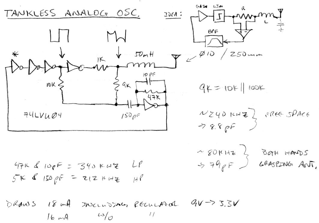
If you play around with series resonant LC circuits and a scope long enough, you may notice that the square wave voltage "droops" across the drive resistor at resonance.  This is because the L doesn't immediately draw current, only after a lag of 90 degrees is the full L current drawn.  It goes back to zero at 180 degrees and then switches polarity for the other half of the cycle.  Early on I thought this might be a good way to sense resonance, but somewhat abandoned it along the way.  But for purely analog tankless designs it might be just the ticket because it gets you around all the phase shift issues the series tank has.  The feedback is 180 degrees out of phase which is easily fixed in a non-frequency-dependent way with a simple inverter.  Gobs of gain can be used which tends to ensure startup, no stalling during use, and relatively constant antenna voltage.  And the sense circuitry can be co-located with the rest of the oscillator circuitry, some distance from the simple inductor.

The trick then is to differentially sense the voltage across the drive resistor.  Ideally one would employ a high speed opamp to do this, but I've found a simpler method using CMOS logic.  It works best if high speed logic with good current drive is used, because any transport delay will cause glitching, and the logic output impedance needs to be quite a bit lower than the drive resistor.

Here is the circuit, which I have developed mainly by just tinkering around on my breadboard:

A logic gate is used to invert the drive (the node pointed to with a square wave), and this is compared to the voltage dropped across the drive resistor (the node pointed to with the "droopy" square wave) through a resistive summer.  This goes through a capacitor to the virtual ground summing node of a linearly biased inverter, which forms a high-pass section.  A second high pass network in the feedback path gives us a low pass response (you always get the inverse function when it is in the feedback path) as well a convenient and necessary biasing of the input about the threshold of the inverter.  So we have a bandpass filter set to 340kHz on the top end and 212kHz on the low end.  Another way of viewing this is as a lead/lag network, and I actually set the capacitor values by watching the scope and centering the "droop" point with the antenna in free-space.

Three inverters follow the BPF and serve mainly as a gain block.

The true test with any Theremin oscillator is what the heck happens when you grab the antenna with your hand.  My antenna has a layer of heatshrink on the outside, but grabbing that with both hands (~80pF) doesn't make the oscillator go squirrely.

The BPF introduces a somewhat frequency dependent element in the response, but it can likely be set to accept a wide variety of fairly standard antennas without losing too much in the way of sensitivity.  The inductor is a Bourns 6310.  The circuit works fine on a breadboard which has relatively high interconnect capacitance, on a PWB it may behave differently.  The output is a logic level square wave that can be easily heterodyned with diodes or an XOR gate or similar.  If using two oscillators in close proximity (e.g. pitch & volume) one should probably somewhat differently size the inductors so that the operating frequency ranges differ, and each oscillator should use it's own logic IC for good decoupling (there are six inverters in the 7404).

No doubt the above circuit could be improved.  True high speed differential voltage sensing of the drive resistor ends (i.e. current) would be ideal.

Note that this design is "tankless" - that is, there is no separate resonant LC driving an L in series with the antenna as in most Theremins.  What is sensed is the resonant point of the simple L in series with the antenna+hand capacitance.  Since the LC isn't significantly loaded I believe it likely approaches maximum sensitivity (in a delta Freq / delta pF sense) and so might be a viable candidate as the analog front end of an otherwise digital Theremin.

I also recommend the drive end (left end in the schematic) of the inductor have a LittelFuse SP721 or similar connected to protect the CMOS from ESD.

[EDIT]Hmm, I'm seeing several hundred ns of jitter (phase noise) viewing the output 1ms from the trigger point.  It looks HF but I don't have a convenient way to characterize it.  If it is HF it could be filtered with a PLL (either digital or analog) but with an obvious increase in complexity and cost.  The main reason I left this type of resonance sensing was due to a comparison glitch happening near the crossover point (which was much worse with 4000 CMOS).

[EDIT]Oops, I accidentally left one inverter out of the loop in the schematic.  I fixed this and added a conceptual block diagram to hopefully make things clearer.

[EDIT]The phase noise seems perhaps environmental?  When I lay the oscillator down on the bench the noised is quite diminished - due to more bulk capacitance on the antenna?  I also tried configuring the inverter after the differential / BPF stage as a second BPF but that didn't seem to change the noise amplitude much, if at all.

Posted: 12/11/2013 12:53:40 AM
dewster

From: Northern NJ, USA

Joined: 2/17/2012

Ooh, I need a break from the analog world!  :-)

Mainly working on my Hive processor lately, adapting old verification code (it verifies OK) as well as division, square root, log2, exp2.  When a processor has a one cycle multiplication then division and square root can be performed most efficiently using a binary search rather than the shifting and adding/subtracting things you find in textbooks.  Also, unlike the shifting algorithms, binary searches "fit" in standard width registers.  Win/win!

In the back of my mind I've also been thinking about the LED tuner.  One thing not taken into account with linear LED PWM techniques is the non-linear response of the eye.*  I think this makes relative darkness easier to perceive than relative brightness.  Also, if a single LED is lit then it's hard to tell where it is in the pattern unless the LEDs are physically exposed to view, which is problematic for mounting, and can lower their contrast ratio because they can't be located behind a colored filter.

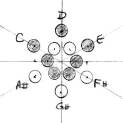
So my next approach will be to have all the LEDs a single color, and have them all lit except for a "dark spot" that moves around.  A circular arrangement makes the most sense obviously because of the repeating nature of octaves.  Here is what I'm thinking:

The shaded LEDs are no different than the others, they represent the C/Am (natural) scales.  The symmetric pattern may be highly useful to players. The display could be red LEDs beneath a red bezel thus enhancing contrast, and no need for an exponential (or power, the eye is really complicated) LED response.

I'd be particularly interested in what players think of this idea, but of course welcome all feedback.

* http://www.telescope-optics.net/eye_intensity_response.htm

[EDIT] I'm assuming an increase in pitch should cause clockwise rotation on the display - is this the most natural seeming arrangement?

Posted: 12/11/2013 11:20:41 PM
dewster

From: Northern NJ, USA

Joined: 2/17/2012

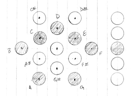
Another tuner layout:

The previous one rotated 30 degrees.  I think I like this one better, the pattern is similarly symmetrical for C & Am.  C is a little buried, but A is right out there.  I'm thinking the center LED could be used to show how close one is to a semitone, with completely dark = centered on the note.  As above, all the LEDs would be lit, with darkness showing the active position.

On the right is an octave display.  5 LEDs might be enough here with a looping around for the octaves beyond the nominal 5 octave range.

I wonder if this could be used as a keyboard layout?

You must be logged in to post a reply. Please log in or register for a new account.