Let's Design and Build a (mostly) Digital Theremin!

Posted: 2/11/2014 5:24:03 PM
FredM

From: Eastleigh, Hampshire, U.K. ................................... Fred Mundell. ................................... Electronics Engineer. (Primarily Analogue) .. CV Synths 1974-1980 .. Theremin developer 2007 to present .. soon to be Developing / Trading as WaveCrafter.com . ...................................

Joined: 12/7/2007

I am not sure I understand the above..

2.7MHz / 4096 = 659.18

2.5MHz / 4096 = 610.35

So I dont see where the 150 and 165 Hz comes from...

But assuming I am missing something, and you do get 150 to 165 Hz range and 6.0 to 6.6ms to acquire the count, I still do not see how you get "a variable tradeoff between resolution and speed!"

Seems to me you are going to have a minimum access time of 6ms - which IMO is probably just passable, but I wouldnt really be happy with any latency longer than about 3ms.

With a heterodyning system "null biased" at 1kHz, one gets (much) greater resolution and maximum access latency of 1ms...

Ok - Im not into all the other digital stuff - but pre-heterodyning has always seemed like a no-brainer to me..

Fred.

Posted: 2/11/2014 6:09:43 PM
livio

Joined: 2/2/2014

Yes there was an error in the divisors values, now it is correct, thanks for this.

The variable tradeoff is explained in the table, changing the divisor you can get more or less resolution and more or less speed, as you prefer.

This method works perfectly, very fast and with absolutely precise tuning.

--------------------

Please, indicate the method you use and the frequencies to let me calculate your resolution.

Posted: 2/11/2014 6:52:27 PM
dewster

From: Northern NJ, USA

Joined: 2/17/2012

"The variable tradeoff is explained in the table, changing the divisor you can get more or less resolution and more or less speed, as you prefer."  - livio

Not trying to knock your method, and I've found in my prototype that these direct approaches give "good enough" resolution.  While literally any approach can be made to trade better resolution for higher latency, the trick IMO is to get both high resolution and relatively low latency simultaneously.  You could use a variable low pass filter that reduces its cutoff frequency as you play farther from the antenna (I was going to look into this before I started down the heterodyning path).

But I believe heterodyning can do better.  I keep pointing out that this is exactly what FredM and I have just recently been discussing in this thread (livio, please read back a few pages).

"This method works perfectly, very fast and with absolutely precise tuning."

Yes, well, if you don't look too closely at what the environmental capacitance or the temperature dependent inductance are doing.

"this is not possible with heterodining, because of the additional - unknowable - manual trimming amount)"

AFAIKT, heterodyning itself doesn't preclude knowing anything.  The trimming amount can certainly be known if you are generating the local oscillator digitally.  Given that you can work backwards to the capacitance.

Posted: 2/11/2014 8:21:04 PM
livio

Joined: 2/2/2014

I don't either want to "knock" your methods, you and Fred are doing a fantastic job and I am proud to participate in your research. What I'm trying to do, is to obtain the maximum, from simplification.

Consider this: you said you've tried it and it was "good enough", but you have tested it at 300 kHz. Instead, using a 3MHz oscillator, you get ten times more resolution (speed). 

Ten times better than "good enough", seems great to me.

The advantages of not using the heterodyning are many, it seems to me that you're still suspicious, but we'll talk about this, in the next posts.


Posted: 2/11/2014 8:49:11 PM
livio

Joined: 2/2/2014

There's also a simple way to build an all digital etherodyning, that can be easily implemented, by modifying the CapSensor firmware.

1 ) We slow down the frequency of the oscillator to the usual 300kHz (suffering a little bit)

2 ) Then we program the ADC to sampling at 300KHz or close, as in your projects. (PIC's ADC, ranging up to 500 KHz)

3 ) The ADC samples the oscillator at regular times and produces a series of bytes, that represent beating (heterodyning between the ADC sampling frequency and the oscillator frequency)

4 ) The ADC has a FIFO buffer, then it is easy to read samples, without timing difficulties.

5 ) Then we count our 32 MHz clock until ADC samples have high values and then return to low values.

6) We repeat this for an integer number of cycles, until adequate time has passed (about two milli seconds).

7) In practice, this is a multi-period meter (as opposed to a frequency meter and better than a period meter).

8 ) With the inverse of the final count, the ADC sampling frequency and the number of multi-periods, we calculate the heterodyning frequency.

9) Finally, we integrate the frequency for about 2mS, with a "moving average" filter, to emulate the hardware low-pass filter.


Posted: 2/11/2014 9:50:05 PM
FredM

From: Eastleigh, Hampshire, U.K. ................................... Fred Mundell. ................................... Electronics Engineer. (Primarily Analogue) .. CV Synths 1974-1980 .. Theremin developer 2007 to present .. soon to be Developing / Trading as WaveCrafter.com . ...................................

Joined: 12/7/2007

livio,

I think one can instantly see how heterodyning is hugely superior if you think about it this way..

Whatever your frequencies are (for the antenna oscillator) you are not going to get a deviation of more than perhaps 10% as a result of (wanted) player / control capacitance..

So one must capture "data" which is 90% redundant - as in, any clock used to count the period of a directly devided HF oscillator must be ~10 times faster than a clock used to count the period of a heterodyned signal (where the difference - ie ONLY the wanted is pre-resolved) in order to get similar resolution to that obtainable from a heterodyned (difference) signal.

My focus has been on analogue, so actual counting of period in order to derive a digital value is something I only have limited expierience of - however I have done some work in this area - originally 6 years ago when I was heading the digital route, and more recently to extract data in digital form for other functions.. My method was to take both reference and variable oscillators and independently multiply these with PLL's, and then heterodyne the results.. Using a *10 multiplier, the difference frequency (after heterodyning) is 10* the audio frequency of the unmultiplied oscillators (the oscillator difference frequency) ... So a 20Hz audio gives a 200Hz multiplied frequency that can be measured directly with a fast clock, and has low latency (5ms for a 20Hz audio, 500us for a 200Hz audio) -

One can (as you can) reduce the PLL multipliers to get higher resolution - a *5 multiplier is about the lowest acceptable, giving a 10ms latency @ 20Hz (audio) (the multiplied difference being 100Hz) and reducing as frequency increases (at 100Hz audio, multiplied difference is 500Hz, latency is 2ms - at 1kHz audio, multiplied d = 5kHz, latency = 200us)

I use the above system mostly to drive analogue period to voltage circuits (to derive a CV output) - as this scheme allows tracking of the theremins output frequency right down to 16Hz at low latency (unlike converters that act on the theremins pitch, and dont work below about 100Hz) -

If I was to seriously go to a digital "engine" I would probably use the above scheme with an ADC (as this would allow me to retain at least one beloved analogue heterodyned voice ;-) - probably using the MCU/FPGA to perform the exponential conversion (at present I use analogue exponential converters which are a pain) for any digital voice pitch resolution, CV output, and On-Key-Emphasis (which is my main reason for looking at digital at all).

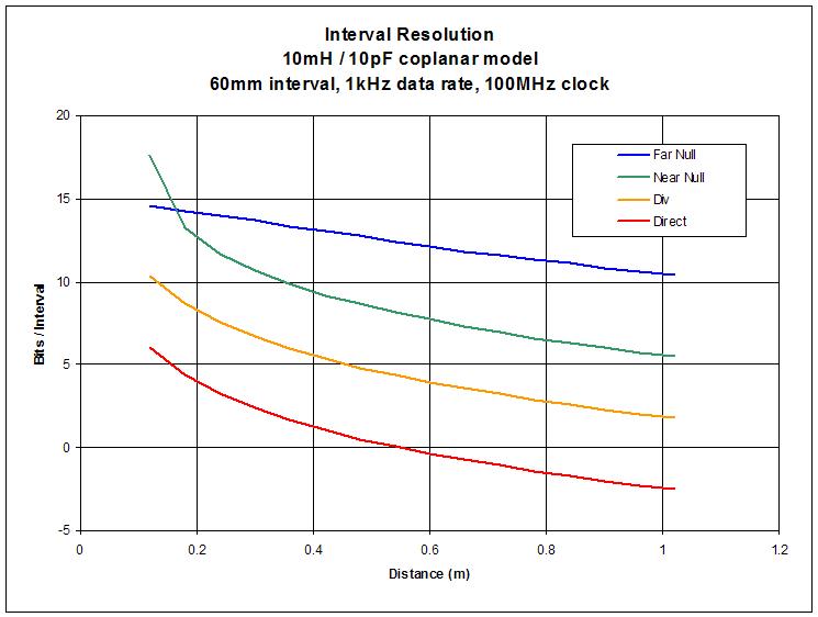
But, at the end of the day, with a biased offset frequency heterodyning system, one gets effectively what I get using frequency multiplication (and from Dewsters plots, it seems you get great improvement in linearity) and the concequential low latency and high resolution..

I want to keep my conventional analogue heterodyning voice, so "biasing" the "null" point is not an option for me.. But for "grabbing" data if you are not using the heterodyned difference for direct output, I can see no other method which comes anywhere close..

Please note though - I am not a digital "guru" and I am a mathematical moron, so much of what you and Dewster have been discussing is at the edge of my full comprehension.. It is entirely possible that my calculations are wrong, or that I am missing something  ~ but right now I have no idea what that might be if I am ..

Fred.

"Please, indicate the method you use and the frequencies to let me calculate your resolution."

The frequencies I use for my oscillators is almost irrelevant - but because I like to keep my PLL oscillator frequencies well below 8MHz I tend to run somewhere 'round 500kHz (I also do mixed signal register switching, which involves division of the oscillator frequencies - so dont run much below 400kHz, as the resultant divided frequencies become more difficult to filter if they drop below 100kHz)

There is no relationship between oscillator frequency and resolution - there is only a relationship between difference frequency / clocking frequency and resolution.

"For me a true Digital Theremin should't use hetherodyning and audio signal."

LOL ;-) .. So now were getting a whole new dimention ;-) Once we were arguing about what a "true theremin" was, and digital certainly didnt qualify, now were going to argue about what a "true Digital Theremin" is - And try to say that the most efficient method of deriving the required data is not usable for this new evolution, because its "unworthy" of the digital "ideal"..

Im putting my analogue jacket on and going for a walk down my analogue street - oh, not to forget my analogue wellies for the floods from the analogue river that has overflowed due to the analogue weather patterns we have completely fuc*ed up on the way to our digital utopia..

Posted: 2/11/2014 11:25:16 PM
FredM

From: Eastleigh, Hampshire, U.K. ................................... Fred Mundell. ................................... Electronics Engineer. (Primarily Analogue) .. CV Synths 1974-1980 .. Theremin developer 2007 to present .. soon to be Developing / Trading as WaveCrafter.com . ...................................

Joined: 12/7/2007

livio -

Been racking my brains trying to see how you get your numbers, and I just cant see any of it!

I hope you can explain:

Taking your numbers..

2.5MHz / 16384 = 152.59 = 6.554ms ... 6.554ms / 32MHz = 209715 counts.

2.7MHZ / 16384 = 164.79 = 6.07ms ... 6.07ms / 32MHz = 194180 counts.

The usable counts are 209715 - 194180 = 15534.

I can only see a resolution of 15534, (15.5k) not the 200000 (200k) shown in your chart.

The 200k resolution is the sort of numbers you get (using a 32MHz clock) if you heterodyne, because you are only dealing with the difference and not having to deduct the common (baseline) count.

Wrong ->

Even with heterodyning, 32MHz is IMO not fast enough to combine acceptable latency with acceptable resolution - perhaps its right on the edge of acceptability, but no more than that.. I have used 48MHz but the FPGA's (or faster MCU's) look far better suited because their clock frequencies can be substantially higher.

<- Wrong

Oops.. of course, my method (multiplying the difference) results in much higher difference frequencies, and my thinking is along these lines and the sums I have done for this method.. When using unmultiplied difference, the clock requirement will be lower... even a resolution of 15.5k derived from a 32MHz clock if exponentiated correctly probably gives acceptable musical resolution.. but IMO the 6ms required to obtain this is too long.  

Fred.


Posted: 2/12/2014 12:05:47 AM
dewster

From: Northern NJ, USA

Joined: 2/17/2012

"What I'm trying to do, is to obtain the maximum, from simplification."  - livio

Definitely, same here.

"Consider this: you said you've tried it and it was "good enough", but you have tested it at 300 kHz. Instead, using a 3MHz oscillator, you get ten times more resolution (speed)."

I've tested something like what you are doing with a ~120 kHz LC oscillator and 100 MHz digital clock.  I didn't divide down, but instead obtained the frequency offset from the digital phase locked loop and low pass filtered it to ~1kHz.  I then subtracted this from a fixed number to get an audio pitch number which I fed to an numerically controlled oscillator.  I relied more on averaging, but I believe the approaches are very similar in results.

"Ten times better than "good enough", seems great to me.

Other than to perhaps minimize interference, and to use a fairly small air core inductor (both good reasons) it doesn't seem like the operating point of your divided approach is at all critical.  Any value L combined with the given C will give you the same % frequency deviation, and once you divide that down it again gives you the same % frequency deviation.  So I guess I don't see any intrinsic benefit to higher frequencies in terms of obtaining more useful data with your divided approach.  10x higher LC frequency doesn't automatically give you 10x more information.

The advantages of not using the heterodyning are many, it seems to me that you're still suspicious, but we'll talk about this, in the next posts."

Oh, I've been avoiding it as much as possible, but can now see that there is likely a huge benefit to heterodyning.

I've been fairly actively thinking about this stuff for going on 2 years now and only lately have some of the most basic concepts sunk into my thick skull.  The simplest examples are the best.

livio, let's use your divided approach.  Say we have an LC running at 2MHz that gives 5% deviation with hand capacitance, or 1.9MHz minimum.  Divide this down to 1kHz and we still have 5% deviation.  If our sample clock is 30MHz we get 30MHz/1kHz=30,000 count.  5% of this is 1500 or ~10.5 bits of information.

Now let's look at the heterodyning approach with the same oscillator above beating against a 2.001MHz local oscillator.  2MHz gives 1kHz, 1.9MHz gives 101kHz.  The first gives us 30MHz/1kHz=30,000.  The second gives us 30MHz/101kHz=297,030.  The difference is 267030 or ~18 bits of information.  Other than the dramatically increased resolution, the largest period count happens in the far field where the resolution is pooping out in your divided approach.  And sticking a low pass filter on there can further increase the resolution near the antenna (not that we need it, but it seems to be free so why not). 

There may be some huge practical downside to heterodyning, but I'm not seeing it on paper (yet).  With the divided approach you will always be fighting stray capacitance, trying to squeeze every last bit of sensitivity out of the thing, setting averaging times a little too long in order to get better numbers.  The divided approach certainly works, and decent performance can be coaxed from it, but it's right on the edge IMO, even with a really fast digital clock to work with.

Here is that chart again:

Not modeling your exact circuit livio, but given identical components you can see the resolution difference between the offset heterodyning method (blue line) and your division method (yellow line).

Posted: 2/12/2014 1:23:56 PM
FredM

From: Eastleigh, Hampshire, U.K. ................................... Fred Mundell. ................................... Electronics Engineer. (Primarily Analogue) .. CV Synths 1974-1980 .. Theremin developer 2007 to present .. soon to be Developing / Trading as WaveCrafter.com . ...................................

Joined: 12/7/2007

Dewster -

This is probably more for the "crazy ideas" thread..

We were talking earlier about 'digital' heterodyning, and you exposed a fatal flaw in my D-Latch scheme which causes  resolution to be lost and therebye far less useful than I had thought for count capturing..

This has been bugging me - been thinking of all kinds of crazy ways to avoid having to depend on filtering and zero-crossing detection..

One idea keeps coming back, but I have no idea how to implement it, and am not even sure it wont have a quantization problem (in fact, I am starting to wonder if one really gets rid of the quantization issue even with analogue filtering - wondering if one is actually just "smudging the lines" rather than getting higher actual resolution) - but here it is anyway..

From an XOR fed from Ref and Var, one gets a stream of pulses increasing then decreasing in width, which, when integrated, produce a triangle waveform. The zero crossing point from an integrator following these pulses should occur (?) exactly when the pulses have an equal M/S ratio (or at least be synchronous to this event).

If one was able, digitally, to recognise the 50/50 'event' would this be any better than the D-Latch ?

I am undergoing a bit of a brain melt-down over this matter.. At present, as I see it, unless one goes for a true analogue multiplier driven with sine waves  (and this is not without its difficulties) any filter accepting the results of "digital heterodyning" must be getting a signal which is locked to the (logic edges of) oscillators feeding this heterodyning (please tell me im wrong!)-: and therefore any percieved "improvement" cannot be anything more than integration of the noise / jitter components - None of this probably matters for producing audio, but for capturing accurate cycle-by-cycle digital data, I suspect that it could matter..

I have used my D-Latch primarily for wave-shaping, and had no problems.. But I have also used it to determine period of my multiplied difference frequency, using a linear integrator (producing, after S+H, a voltage), and have not noticed problems - but there should have been problems! ... So I now suspect that its been jitter that has "improved" resolution - the jitter being integrated "away" in the process of the period to voltage conversion..

Trouble is that Ive used the above on some rather critical (fortunately not safety critical)  non-musical applications - (although I never did the digital stuff, only the front-end, the "ref" and "var" oscillators were fed to a FPGA and a D-Latch implemented in this, from which numeric data was obtained) its been one of those moments of horror when I realised that I had missed something utterly bloody obvious - so caught up in enthusiasm for my simple "solution" that I failed to do full and proper evaluation of it.

I need to go back to treating every design as if it was safety critical, I dont make these kind of mistakes when I do that..

Fred.

Posted: 2/12/2014 3:10:50 PM
livio

Joined: 2/2/2014

The (CapSensorHQ) usable counts are 209715 - 194180 = 15534 - FredM

Yes, this is more or less the resolution that we have now and the theremin sounds good with it. I'm preparing a video, showing that you can take notes perfectly centered and that the response rate is reasonably high. You must also keep in mind that this resolution is constant at any frequency (as with the heterodyning the resolution is variable depending on the tuning)

Heterodyning is hugely superior - FredM
I guess I don't see any intrinsic benefit to higher frequencies - dewster
You can see the resolution difference between the offset heterodyning method (blue line) and your division method (yellow line) - dewster

Your arguments are correct, I do not dispute any of the points that you have perfectly illustrated.

Likewise, I invite you to consider, that are possible excellent alternatives, based on pure counting. If the performance of our CapSensor seems to you not enough, you could measure the period, with an higher frequency than our current 32MHz .

------------------------

What bothers me most about heterodyning, is not the theory but the following practical problems:

1 ) The oscillator must be low frequency (not sure of this, correct me if I'm wrong ) while the entire history of electronics demonstrates the advantages of using higher and higher frequencies.

2 ) It is easy to get out of the useful range of frequencies and in that case, you have to retune the oscillator.

3 ) Almost certainly you have to add a oscillator capacitive trimmer, to be factory calibrated (hopefully only at the factory... but I think in practice, the user himself will have to adjust it, every time either the antenna position, or the nearby objects position have changed)

Maybe you are able to indicate solutions to these three points (without digitally adjustable capacitors or other oddities) and I could convert me to the heterodyning (with a new firmware version, as written in one of the previous posts) Probably naming it CapSensorHT, even if we continue to maintain the CapSensorHQ, that has fewer tuning problems and greater immunity to ESD events.

-----------------------

I realized now that our views are slightly different. This is because you are reasoning mainly about the Theremin (and rightly so) while we think of our CapSensor as a generic "Proximity Physical Interface" (to protect objects in museums and other similar applications), even working very well to build Theremins.


You must be logged in to post a reply. Please log in or register for a new account.