Let's Design and Build a (mostly) Digital Theremin!

Posted: 2/12/2014 4:40:00 PM
FredM

From: Eastleigh, Hampshire, U.K. ................................... Fred Mundell. ................................... Electronics Engineer. (Primarily Analogue) .. CV Synths 1974-1980 .. Theremin developer 2007 to present .. soon to be Developing / Trading as WaveCrafter.com . ...................................

Joined: 12/7/2007

" If the performance of our CapSensor seems to you not enough, you could measure the period, with an higher frequency than our current 32MHz ."

Livio,

I am certainly not trying to "bash" your sensor or ideas.. Hell, theres one thing I have learned from playing with theremins, and that is that every time one thinks youve "got it" something comes along to show you that, well, you perhaps got a bit more of the picture - but any kind of certainty that you have "the best" approach is likely to lead to dissapointment.

I started off about 8 years ago doing things quite similarly to you - and where I am today is the result of much tribulation and boxes of circuit boards I thought would be "the one" but never made my grade..

IMO, what makes this moment somewhat special is that suddenly several digital theremin designs / topologies are "on the table" .. For me, this is more a "spectator" matter - I went back to analogue long time ago, and digital stuff for theremins only has a real interest for peripheral functions..

But we now have a situation where we can actually look at digital topologies and start to complare them.. We dont know much about the theremini, We have wonderfull in-depth design and analysis from Dewster (most of the digital stuff in this being above my head) We have full disclosure of your theremino designs and software (and I really applaud you for this) and we have  full disclosure of the Open.theremin designs and firmware..

"I realized now that our views are slightly different. This is because you are reasoning mainly about the Theremin (and rightly so) while we think of our CapSensor as a generic "Proximity Physical Interface" (to protect objects in museums and other similar applications)"

I think there is truth in this - I think those of us who get "caught" in TW and/or get to see classical thereminists playing, and are foolish enough to engage in making a better instrument than those on the market at present, are certainly focussing on something requiring far lower latency and far higher resolution and linearity than what is required for most capsense applications - And also, it certainly is true that most casual users of the theremin dont need much more than a "generic Proximity Physical Interface".

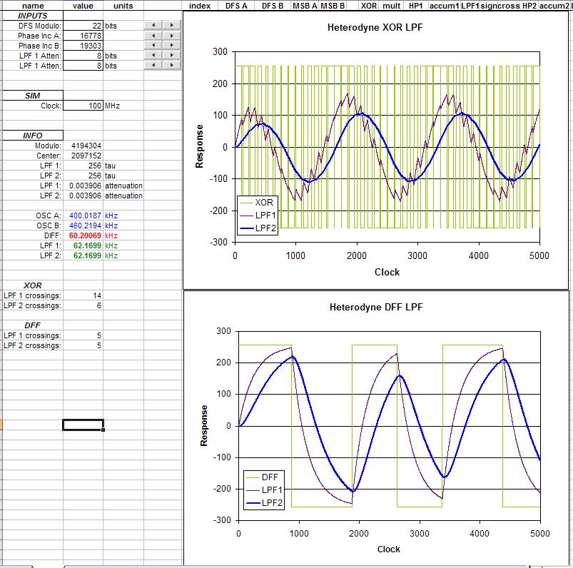
My present opinion is that the best digital theremin topology I have seen (in terms of the front-end / data aquisition ) is the Open.theremin - If Dewsters linearity simulation is correct (and it does seem to be) then the combination of speed and resolution possible by using heterodyning in the way this does is a big step forward.

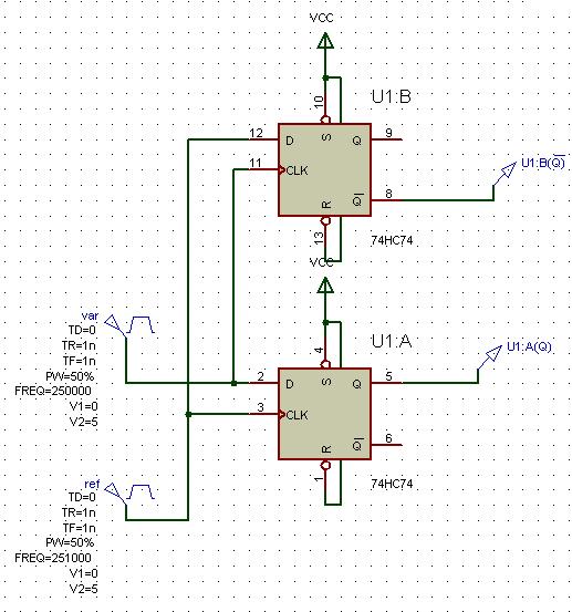
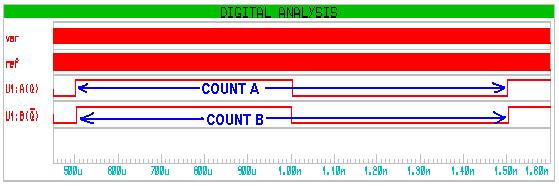
I am also interested in your higher frequency of operation - I think this could be an advantage for reasons different to the ones you present - I think that combined with D-Latch heterodyning it may be possible to get close to the resolution of the Open.theremin without needing analogue filtering after an XOR mixer.. But I havent really explored this yet.

Down at my core though, I know Lev Theremins original concept cannot be beaten - He was there with the solution 90 years ago, and nothing I have seen has come close - particularly in terms of speed and resolution - and I think that if the theremini uses analogue heterodyning, it may actually manage higher resolution than any digital scheme could - but I suspect it doesnt !

Fred.

What bothers me most about heterodyning, is not the theory but the following practical problems:

1 ) The oscillator must be low frequency (not sure of this, correct me if I'm wrong ) while the entire history of electronics demonstrates the advantages of using higher and higher frequencies.

No, the limit is set by the mixer - one can heterodyne with input frequencies up in the 10's of MHz if your mixer can handle it, and you can buy analogue multipliers that operate at these frequencies.. Likewise one can do XOR "heterodyning" at high frequencies.

2 ) It is easy to get out of the useful range of frequencies and in that case, you have to retune the oscillator.

To get out of range, one or both oscillators must change - if your oscillators arent stable, this will be a problem whatever topology you use.

3 ) Almost certainly you have to add a oscillator capacitive trimmer, to be factory calibrated (hopefully only at the factory... but I think in practice, the user himself will have to adjust it, every time either the antenna position, or the nearby objects position have changed)

No - I hate capacitive trimmers!!! ;-) A variable inductor is sufficient for factory trimming, and electronic tuning is available for user adjustment (see EW schematic)

Maybe you are able to indicate solutions to these three points (without digitally adjustable capacitors or other oddities)

Directly digitally adjustable capacitors (what a lovely idea ;-) arent needed, there are many ways to tune using a voltage or current - a D/A is all thats required I think..

and I could convert me to the heterodyning (with a new firmware version, as written in one of the previous posts) Probably naming it CapSensorHT, even if we continue to maintain the CapSensorHQ, that has fewer tuning problems and greater immunity to ESD events.

IMO, IF you want to compete at the high end, you may need to do this... But one word of personal bitter caution - Economically, there is NO return for targeting the high-end - Unless you are brilliant, getting things "right" will consume all your resources and leave you a twisted jibbering wreck like me!!!  ;-)

 To be honest, I dont think its possible to have a simple answer to all the above for the "high end" - But my area is analogue - perhaps with digital tech you can make a unit which isnt complex to set up and performs well ... The Open.theremin seems to be getting there by all accounts.. but I leave that for others to comment on..

Posted: 2/13/2014 8:37:04 AM
livio

Joined: 2/2/2014

To get out of range, one or both oscillators must change - if your oscillators arent stable, this will be a problem whatever topology you use. FredM

Our oscillators are stable! But with the topology you propose, it would be sufficient to change the lenght of the antenna, from 10 cm to 1 meter, to go out of range. I do this frequently.

The heterodyning topology goes out of range, even when changing the antenna (connecting the sensor to a different antenna) and tuning frequently an inductor with a screwdriver, would be very annoying.

Instead, the modulararity of our system, permits to add any number of antennas, to play polyphonic, polytimbric and also poly-instrumental. (poly-instrumental means that you can play in "ThereminClassic mode" one antenna, while playing in "Pizzicato" another antenna and while sending a third antenna to an external MIDI or CV-Gate Synth)

Soon I will publish some video about. 

oops, I forgot... not only polyphonic, polytimbric.. but also "Stereo", CV-Gate, MIDI, OSC, Voices and Banks user programmable, Wavetables, ADSR, Chorus, Echo, LFO, with the ability to save and restore configurations. And finally, to connect other devices, like classic resistive pedals, ribbons, optical sensors, magnetical sensors and capacitive keys, also with velocity.

No one of the commercial Theremins, can do all we can, not even the Moog Etherwave. Perhaps we are different in some characteristics, but already "competing at the high end" (to use your same words)    ;)

Posted: 2/13/2014 10:29:28 AM
livio

Joined: 2/2/2014

Dewster,
would you please, explain me some details?

I'm setting the firmware to follow your ideas, but I'm not able to understand, how you intend to make the final conversion. Even theoretically, using your method, high notes resolution, it's still too low.

Let's leave aside the oscillator, the frequency of comparison, the mixer and the possible low-pass, which clearly work.

Let's just have a precise account of heterodyned frequency, ranging from 1 kHz (hand away) to 10 KHz (hand close)

How will you measure a 10 kHz, in a time of 1 or 2 mS, with a resolution sufficient to tune high notes, perfectly?

With "perfectly tuned" I mean that you can play two high notes (at least 5 KHz), with two different Theremins, and tune them so that, the beats between the two notes, are so slow as to be almost inaudible (at least ten seconds for the whole cycle of the beat)

Our Theremin do this perfectly and I would not worsen this characteristic, as a function of an exaggerated response speed that, in practice, could add little to the playability of our instrument. (I'm preparing some videos that show either the perfect intonation or the sufficient speed of response)

Posted: 2/13/2014 2:12:56 PM
dewster

From: Northern NJ, USA

Joined: 2/17/2012

Brain's kinda sluggish lately with lack of sleep, all the snow shoveling, boiler repair in the dead of winter, etc. - but I'm trying to keep up with this thread!

"There's also a simple way to build an all digital etherodyning, that can be easily implemented, by modifying the CapSensor firmware.

1 ) We slow down the frequency of the oscillator to the usual 300kHz (suffering a little bit)

2 ) Then we program the ADC to sampling at 300KHz or close, as in your projects. (PIC's ADC, ranging up to 500 KHz)

3 ) The ADC samples the oscillator at regular times and produces a series of bytes, that represent beating (heterodyning between the ADC sampling frequency and the oscillator frequency)

4 ) The ADC has a FIFO buffer, then it is easy to read samples, without timing difficulties.

5 ) Then we count our 32 MHz clock until ADC samples have high values and then return to low values.

6) We repeat this for an integer number of cycles, until adequate time has passed (about two milli seconds).

7) In practice, this is a multi-period meter (as opposed to a frequency meter and better than a period meter).

8 ) With the inverse of the final count, the ADC sampling frequency and the number of multi-periods, we calculate the heterodyning frequency.

9) Finally, we integrate the frequency for about 2mS, with a "moving average" filter, to emulate the hardware low-pass filter."  - livio

Brilliant!  Aliasing is heterodyning!  And aliasing a sine wave in this manner should give another sine wave with no upper harmonics to worry about (though low pass sampling at the end wouldn't hurt)!

"I'm setting the firmware to follow your ideas, but I'm not able to understand, how you intend to make the final conversion. Even theoretically, using your method, high notes resolution, it's still too low.

Let's leave aside the oscillator, the frequency of comparison, the mixer and the possible low-pass, which clearly work.

Let's just have a precise account of heterodyned frequency, ranging from 1 kHz (hand away) to 10 KHz (hand close)

How will you measure a 10 kHz, in a time of 1 or 2 mS, with a resolution sufficient to tune high notes, perfectly?"

If you have a 32MHz clock, you can resolve 10kHz to 32MHz/10kHz=3200 or 11.6 bits at a 10kHz rate.  Low pass filtering this down to 500Hz gives you another (10kHz/500Hz)^0.5=4.5 or 2.1 bits at a 500Hz rate.  For a total of 13.7 bits.

Which doesn't seem like much, but you have to compare it to the "1kHz (hand away)" count, which is 32MHz/1kHz=32,000.  32,000-3,200=14.8 bits of information.

The bulk of the digital resolution gain from heterodyning is produced by keeping the far beat low in frequency to give you a big number when counting clocks.

Posted: 2/13/2014 3:00:04 PM
dewster

From: Northern NJ, USA

Joined: 2/17/2012

"From an XOR fed from Ref and Var, one gets a stream of pulses increasing then decreasing in width, which, when integrated, produce a triangle waveform. The zero crossing point from an integrator following these pulses should occur (?) exactly when the pulses have an equal M/S ratio (or at least be synchronous to this event).  - FredM

If one was able, digitally, to recognise the 50/50 'event' would this be any better than the D-Latch ?"  - FredM

To investigate the DFF better I added it to my previous XOR simulation:

Basically 400kHz and 460kHz NCOs, followed by the mixer (XOR in the top graph and DFF below), then two cascaded first order low pass filter sections.  The green trace is the output of the XOR/DFF, the red trace is the output of the first filter section, the blue trace is the output of the second filter section.  Here the filter cutoff points are set to roughly the beat frequency.  The filters themselves use simple bit shifting rather than multiplication to perform the internal attenuation.

The output of the XOR is like that of a single bit DAC, with lots of high frequency information that is fairly easily filtered away to yield the fundamental - though it takes a second order filter to sufficiently remove the "jaggies" and a simple integrator isn't enough.

The output of the DFF is more problematic to filter into a sine wave because it contains strong harmonics of the fundamental (1, 3, 5, etc.).  More aggressive filtering could turn this into something more like a sine wave, but that might hurt you in a heterodyning scenario where the frequencies going into the filter will vary over a large range, thus impacting amplitude for higher beat frequencies.

One unexpected thing going on here is the DFF mixing of two NCOs gives wildly varying duty cycles!  I think this is the low frequency beating of the NCO output against the clock, but need to check this in a verilog sim before I really believe it.  This kind of crap can totally trip you up digitally because any significant LF content will confound period measurement.

I am undergoing a bit of a brain melt-down over this matter.. "  - FredM

When things are better understood in the frequency domain my brain tends to lock up.  Delta sigma DACs seems like borderline magic to me.  I have to keep remembering that perfect (or perhaps "perfect enough" in the real world of limited resources) reconstruction of analog is always possible given a sufficient sample rate (>Nyquist) followed by sufficient filtering.

Posted: 2/13/2014 3:51:55 PM
dewster

From: Northern NJ, USA

Joined: 2/17/2012

Digitally, it's pretty easy to turn the ramp waveform from an NCO accumulator into a triangle: just invert all the bits when the MSB=1.  One could sample this with the rising edge of another NCO to give a low frequency triangle without all the "jaggies".  Might be able to get away with a first order LPF after this.

[EDIT] Just tried this, surprisingly not much (if any) improvement over XOR, still needs a second order filter.

Posted: 2/13/2014 6:28:29 PM
livio

Joined: 2/2/2014

The bulk of the digital resolution gain from heterodyning is produced by keeping the far beat low in frequency to give you a big number when counting clocks.

Then I must work upside down - 10 kHz (hand away) to 1 KHz (hand close)? 
I understood well?


dewster thanks for your help, arguments are really tough! 
I do not know if I can make it happen ...

Posted: 2/13/2014 6:36:22 PM
dewster

From: Northern NJ, USA

Joined: 2/17/2012

"Then I must work upside down - 10 kHz (hand away) to 1 KHz (hand close)?"  - livio

What you describe is the green line on my graph.

The lowest frequency with hand away should give you the best sensitivity and linearity (on paper).

Posted: 2/13/2014 6:45:57 PM
livio

Joined: 2/2/2014

Ok, the blue line, "far null" (or better far at a low frequency - about 1 KHz)

Posted: 2/13/2014 8:27:40 PM
FredM

From: Eastleigh, Hampshire, U.K. ................................... Fred Mundell. ................................... Electronics Engineer. (Primarily Analogue) .. CV Synths 1974-1980 .. Theremin developer 2007 to present .. soon to be Developing / Trading as WaveCrafter.com . ...................................

Joined: 12/7/2007

"The lowest frequency with hand away should give you the best sensitivity and linearity (on paper)." - Dewster

IMO, not only on paper - one is working with the natural non-linearity of capacitive sensing (reducing the musical non-linearity) when you do it this way, and doing it the other way you are increasing the musical non-linearity..

One can easily expierience this with any uncompensated analogue theremin - its playable (with some difficulty) over perhaps 3 octaves when bass is far (hand away).. retune it so that bass is near and pitch increases as hand distance increases, and I certainly find linearity far worse, and perhaps only one octave playable.

Dewster, many thanks for all the work you have done testing the ideas, and your clear brilliant plots etc..

I am pulling out of this discussion for a while now.. Other life matters are demanding attention, and the temptation for me is to escape by devoting my brain to thinking this technical stuff - but I need to deal with the other stuff, much as I would prefer to stay in the TW pub and get drunk!

;-)


MORE ON DIRECT DIGITAL HETERODYNING:

Following Dewsters identification of a MAJOR problem regarding use of a D-Latch for "digital heterodyning" where one wants to numerically resolve the period, I have been racking my brains to find a solution..

I make absolutely no warranty for what I present here - I have simulated it only, and am not sure I can rely on my digital simulation engine (the mixture of fast clocks and edges, combined with needing to run over ms times in order to derive "difference" events makes life tough)..

But I think this may be a solution:

Use 2 D latches, one triggering on the "Reference" oscillator and latching the state of the variable oscillator, the other triggering on the "Variable" oscillator and latching the state of the reference oscillator..

One gets two square wave outputs, and as far as I can tell, if you sum the periods of these square waves (rising edge to rising edge of each) you consistantly get a period twice that of the correct difference frequency period.

I think that the "quantising" errors of each square wave cancel each other out.. IF this is true, then it should be possible to implement the entire operation digitally without need for analogue - Two counters whose counts are strobed by the related D latch.

I have tried to "simulate" this in Excel, but its taking way too long, I suspect that theres some easy maths that would confirm or disprove the above, but its beyond me without spending ages on researching it - I dont need this function, so cant be bothered - but I would be interested if anyone does prove or disprove it.

You must be logged in to post a reply. Please log in or register for a new account.