Let's Design and Build a (mostly) Digital Theremin!

Posted: 2/24/2014 12:05:34 PM
livio

Joined: 2/2/2014

Dear Dewster and FredM

First of all, thank you for the solid theoretical basis that you have carefully explained, in your (almost 500!) posts. Reading them carefully, have helped us, to better focus the problem and the possible solutions.

We're doing experiments, and collecting the results in a very detailed PDF file. It is about twenty pages long, one for each technique and any aspect, from the antenna, to the pitching coil and the oscillator, all accompanied by calculations, advantages and disadvantages. 

It still will take some time to be reasonably detailed before you read it. Would be great, having you help with a review, corrections and additions.

Given that it may take weeks yet, I have an anticipation that could (possibly) be useful to Dewster, for his FPGA .

-------------------

Obtaining heterodining with sampling 

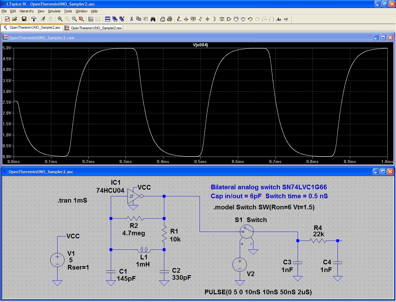
For this technique, an ADC it's not needed, nor starting the process from a sine wave, instead proceed as shown, in the following simulation:

SampleHoldHeteroding - Picture 1 

1 ) We start from a square wave, to avoid being forced to derive the signal from the oscillator circuit. Same as the balance wheel on a good clock, that must be isolated from any influence (some were even built in vacuum), also a good oscillating circuit must be, as much as possible, isolated from the circuit components, that change their capacity with temperature.

2) Instead of using an ADC (which would limit the maximum frequency at around 300 - 500KHz) we use only a Sample-Hold. This way you can rise the frequency at will, to take advantage of small coils, that are stable and with low parallel capacity.

3) A short sample time of about 100 nS (to be adapted to the components and the frequency used) facilitates the subsequent integration given by the low pass filter.

4 ) We add a light filtering, two poles are enough because the 300KHz component to be eliminated, is already very attenuated by the fact that sampling is used, instead of XOR.

5 ) The final signal is already quite large and steep, as to be read directly by a schmitt trigger. For this reason, over the operational circuit of the low pass filter, the squaring components are eliminated, too.

For those wishing to experiment with a hardware sample and hold, the ideal component is the Bilateral Switch, shown in these simulations. Its incredibly short reaction times (a few nano seconds), allow you to rise the frequency as necessary and precisely sampling, regardless of the timing of ON and OFF.

SampleHoldHeteroding - Picture 2

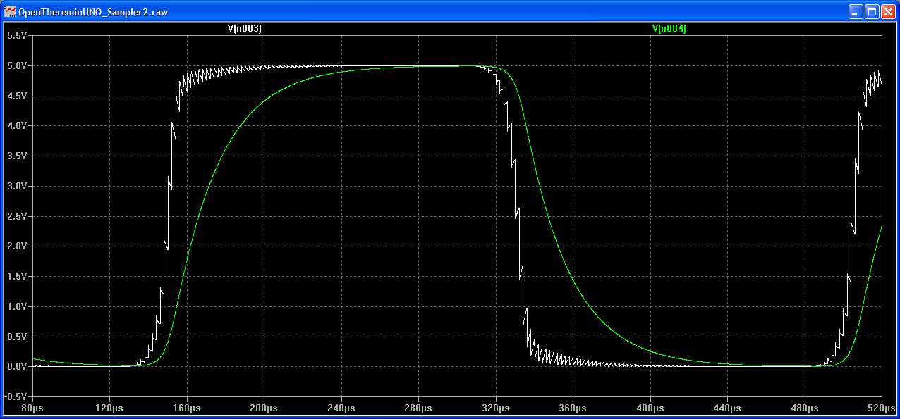
As you can see in this picture, two passive lowpass cells are sufficient. If neeeded, filtering can be increased further by lowering their cut-off frequency. 
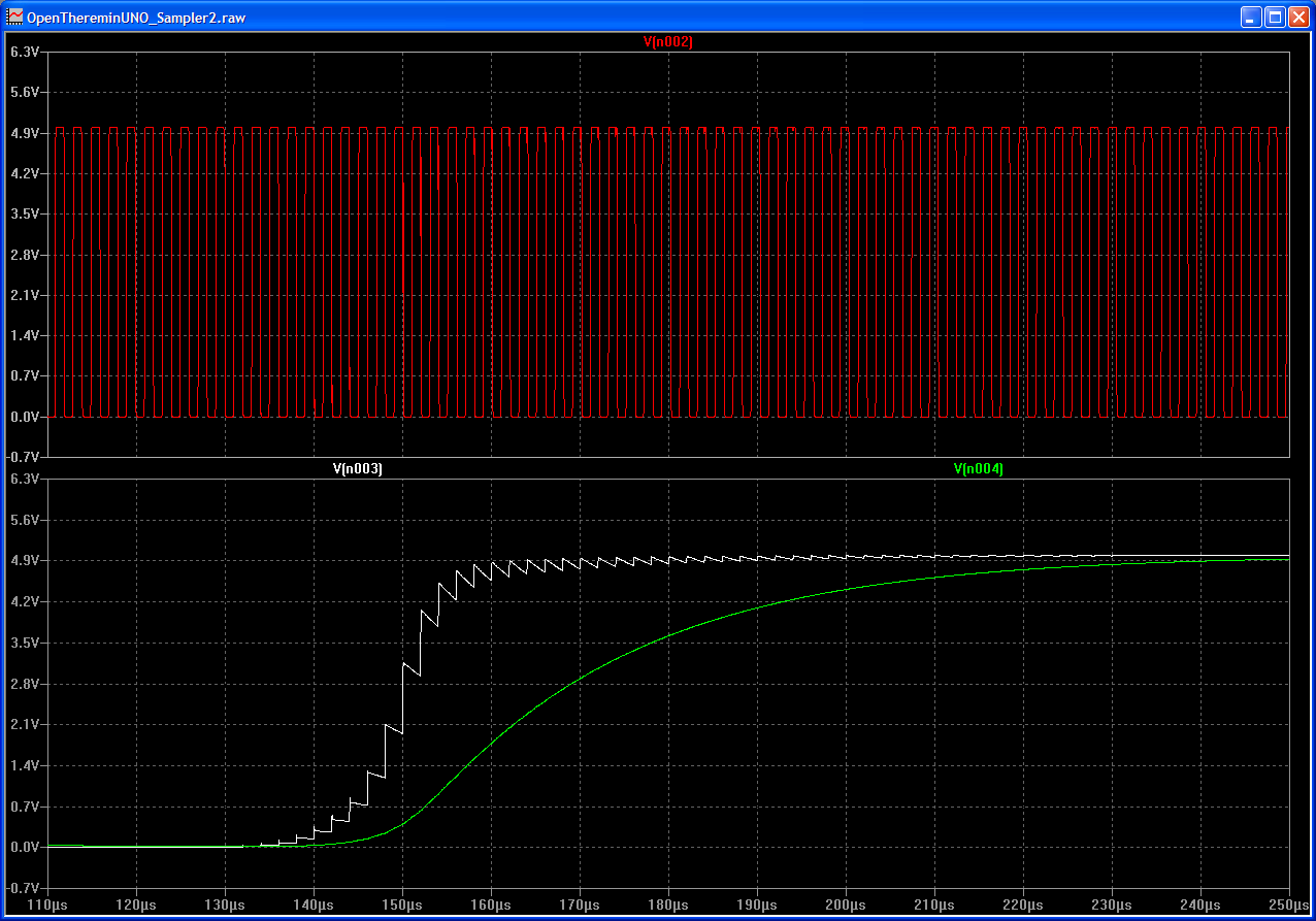
SampleHoldHeteroding - Image 3

RED = oscillator  

WHITE = voltage on sampling capacitor (Note 1)

GREEN = voltage on second low pass cell

(Note 1) The first sampling capacitor, the "bilateral switch" ON resistance and the very short sample time, are all working together to implement the first low pass cell.


Posted: 2/24/2014 12:42:47 PM
ILYA

From: Theremin Motherland

Joined: 11/13/2005

"Obtaining heterodining with sampling" --  livio

Be attentive when reading TW.
This topic has been discussed here: http://www.thereminworld.com/Forums/T/28935/new-mixer-topology?Page=0

Posted: 2/24/2014 3:23:08 PM
dewster

From: Northern NJ, USA

Joined: 2/17/2012

Thanks livio!  But I really want to do this inside of the FPGA digitally, not outside with analog.  In fact, much of the LC oscillator will likely be implemented in the FPGA as well.

So limiting => XOR => LPF => LPF (all of this in logic) seems like it may be the best way to go for my stuff.

Been experimenting with air coils again.  I've found that the sense winding on the end (much like the sense coil you showed a photo of lately for measuring self resonance, Ilya) can be unloaded by making it somewhat resonant.  Higher frequencies appeal to me because the coils get smaller and easier to make, and are thus easier to put inside cabinetry and such, but then the FPGA side of the oscillator gets more time quantized.

Ilya, thanks for pointing to FredM's mixer thread!  I'd somewhat forgotten about it as I wasn't contemplating doing heterodying (or subsampling) at the time.

Posted: 2/24/2014 3:37:08 PM
livio

Joined: 2/2/2014

Be attentive when reading TW.
This topic has been discussed here: http://www.thereminworld.com/Forums/T/28935/new-mixer-topology?Page=0

Be attentive that, though FredM spoke on the same subject, he was referring mainly to the analog world. My post instead is referring to a digital heterodyning with a minimum of analog components, as on previous discussions with Dewster.

Posted: 2/24/2014 5:40:57 PM
ILYA

From: Theremin Motherland

Joined: 11/13/2005

"he was referring mainly to the analog world" -- livio 

score 1:1

Posted: 2/24/2014 5:49:00 PM
dewster

From: Northern NJ, USA

Joined: 2/17/2012

It's kind of too bad they plopped the AM broadcast band smack dab in the middle of the ideal Theremin operation zone.  Deciding whether to go below it or above is something of a conundrum.

I'm pretty sure going below would give stable heterodyning, but going above might get kind of squirrely for heterodyning.  Though if we aren't going all the way to base band (audio) then maybe going above has an overall sensitivity advantage.  I just don't know what to do (cabinetry-wise) with the big honkering coils going below pretty much forces on you.  Big coils are pretty though, and they fairly scream Theremin! when you gaze upon them.

Posted: 2/24/2014 6:39:07 PM
livio

Joined: 2/2/2014

Going above the AM makes possible to work with so little bobbins, that we can decrease the parallel capacity down to 10 pF.

A base capacitance of 10pF modulated by 1 pF (the hand) gives a so great oscillator sensitivity, that we are currently experimenting with an 8 octaves range. With steady notes, 3mS of latency and great temperature stability. Tomorrow we will post some videos that demonstrate these performances.


Posted: 2/24/2014 7:07:33 PM
dewster

From: Northern NJ, USA

Joined: 2/17/2012

10pF (antenna & stray) is about what I'm seeing on my bench with a 0.25m length x 10mm diameter antenna.  A single layer air core solenoid coil wound on 0.75" Schedule 40 PVC (26.67mm outer dia.) using 13m length of #34 AWG (single coat) gives a coil height of ~27mm and 0.45mH inductance, for the combined LC resonance around 2.5MHz.  A coil that small could fit in just about any enclosure.  Put a ~5mm winding on the base to sense resonance.  The issue for me is driving this with a 160MHz quantized square wave, as there are fewer than 100 system clocks per cycle (~64 actually).

A nice thing about physically large coils is they can help to capacitively isolate the drive end from the sense end.

Posted: 2/24/2014 7:36:51 PM
livio

Joined: 2/2/2014

The issue for me is driving this with a 160MHz quantized square wave, as there are fewer than 100 system clocks per cycle (~64 actually).

I suggest to divide the 2.5 MHz by 4096 to produce a 610 Hz (about 1.6 mS)

Then counting your system clock you get 262 000 counts

262k counts are great also when the hand is at 1 meter, also without heterodyning. 

----------------------

Consider that now your oscillator is very sensitive to the hand movements.

before: 1pF on 150 pF = 0.8%

now: 1pF on 10 pF = 10%

Frequency variations are only the root of this, so the sensitivity is "only" 3.5 times increased. 

But 3.5 times are about + 10 dB ! 

And finally, also without heterodyning, you get a yellow line more high then the heterodynized bue line. 

---------------------

Then increasing the antenna area from your 25 cmq to about 200 cmq, you get another + 10 dB, et voilà, our 8 octaves with great stability and great resolution.

Then using our new "dynamic resolution" algorithm... but this is too long to explain now, we are preparing a long PDF about.


Posted: 2/24/2014 10:40:27 PM
dewster

From: Northern NJ, USA

Joined: 2/17/2012

"I suggest to divide the 2.5 MHz by 4096 to produce a 610 Hz (about 1.6 mS)"  - livio

No, detection isn't a problem.  But drive might be: I am driving the tank from an NCO (numerically controlled oscillator) in the FPGA, and the NCO is clocked by a 160 MHz clock.  I could jack this up by doing DDR stuff but it makes the NCO more complicated.

You must be logged in to post a reply. Please log in or register for a new account.