Let's Design and Build a (mostly) Digital Theremin!

Posted: 2/27/2014 8:12:28 AM
livio

Joined: 2/2/2014

"My early test oscillator was 10-20 pF"

Your early test oscillator was 120KHz with 10 mH inductor, if I remeber well. So the total static capacitance was 150 pF, not 10-20 pF. Maybe I have misunderstood the 120KHz and 10 mH? In that case, please, explain this to me.

But I am absolutely sure that OpenThereminUNO has 150 pF of static capacitance and Etherwave even more.

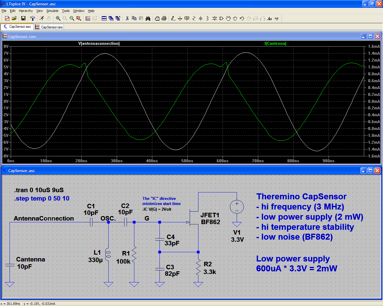
"my newer oscillators have no explicit capacitance other than the antenna capacitance"

Yes, this is the way.

"So the increase in sensitivity you describe is not due to the higher operating frequency."

Yes, using 3MHz is not magical, only a method to reduce (about 100 times) the static capacitance.

"If you are not heterodyning then decreasing the static capacitance and increasing the dynamic capacitance will increase sensitivity the same and regardless of the operating frequency"

Heterodining or not, decreasing the static capacitance and increasing the dynamic capacitance will increase sensitivity, resolution, signal to noise rapport and signal to oscillator stability rapport.

"The vertical axis of that graph is bits/interval"

OK, sorry... I miscalculated because normally I use dB of signal-to-noise.
So the Heterodyning increases the resolution by 4 bit (near) to 8 bit (far) and this means 24 to 48 dB.
Yes this is a dramatical increment of the resolution.

This dramatical increment is important for projects that use a deaf oscillator and an asthmatic processor. But your oscillator is not deaf and your FPGA is hi-speed, so you might do without the heterodyning and all its inevitable disadvantages.

The Heterodining resolution increment is at the expenses of:
- signal to noise ratio
- signal to oscillator instability ratio
- stability (some Khz of change in the oscillator frequency and the etherodining oscillator must be retuned)
- flexibility (difficult or impossible to change the antenna area from 1 cmq to many square meters) 

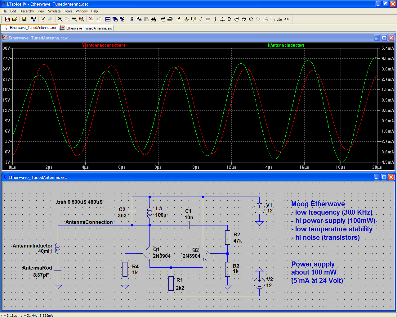
 "Both the EW and your designs have a capacitive antenna as part of a resonant LC circuit."

No, they are only apparently similar.

The "Etherwave antenna system" (antenna8pF & inductor40mH) is a true resonant antenna.

Instead our antenna system is very similar to a capacitor
(and minimally also an antenna, but 1000 times less efficient as electromagnetical waves transducer)

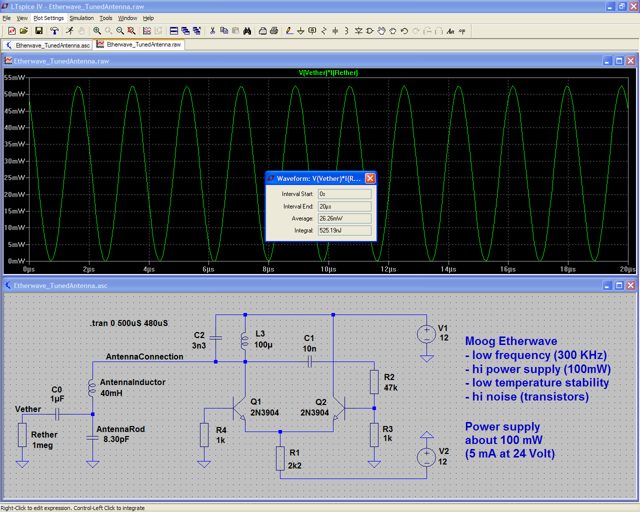
The "Etherwave antenna system" is seen by the oscillator as a pure resistor and the oscillator will dissipates a lot of power on it. And this power is all transformed into electromagnetic waves. 

Instead our "antenna" is seen by the oscillator as a pure capacitor and theoretically, due to the phase shift between current and voltage the power transferred is zero. In practice, even our capacitor, although not tuned with a 40mH inductor, also has a minimum impedance (say a few tens of uH) and this means that there is a minimum emission of electromagnetic waves (50 uW). But this is only a side effect and should be avoided as much as possible (reducing the height, increasing the width and absolutely not using a tuning inductor) 

"That's a factor of ~1,000,000 which on it's face seems not credible"

The ratio between about 50 mW and about 50 uW is only 1000 - not 1 000 000
Consider also that the power is proportional to the square of the voltage (or the current)
So a power ratio of 1000 is simply produced by a ratio of 30 in voltage or current.

I am preparing a precise simulation of the currents, voltages, and phase displacements.
I will post it in some hours.


Posted: 2/27/2014 1:15:36 PM
livio

Joined: 2/2/2014

These two simulations show the antenna Voltages and Currents, for EW and CapSensors

Etherwave_V_x_I

CapSensor_V_x_I

A crude V x I multiplication would give powers of:

Etherwave about 56.9 mW   (4 mA peak * 0.707 * 24 Volt peak * 0.707)

CapSensor about 4.56 mW   (1.1 mA peak * 0.707 * 7 Volt peak * 0.707)

But this crude V x I does not take in consideration the phase displacement between voltage and current.

The Etherwave, having V and I roughly phased, drains about 100 mW from the power supply and delivers 57 mW of them, via the antenna, as electromagnetical energy.

The CapSensor, having V and I phased at about 90 degrees, drains about 2 mW from the power supply and delivers about 50 uW of them, via the antenna, as electromagnetical energy.


Posted: 2/27/2014 9:51:09 PM
dewster

From: Northern NJ, USA

Joined: 2/17/2012

Your simulations above have no mechanism to account for power loss due to RF radiation.

Also, you are comparing voltage and current through a series LC network for the EW (which is not surprisingly almost 0 degrees) to voltage and current through a capacitor for your design (which is not surprisingly 90 degrees).

livio, take a step back and forget about inductors and resonance for a moment. 

Say you have two "antennas": 1) an EW rod shape, and 2) your plate shape.  These form one side of a capacitor; the universe forms the other side of the capacitor but say it is to ground.

Now you hook these antennas up to an AC power source.  For the EW rod we set the power source so the antenna voltage swings 100V @ 300kHz.  For your plate we set the power source so the antenna voltage swings 30V @ 3MHz.  Which one dissipates more power?  If you are modeling the antennas merely as capacitance the answer is neither!  Capacitors are purely reactive components and cannot dissipate any power.  They store energy and release it and that's it.  Same with inductors, and same with inductors connected to capacitors (your EW case).  It takes resistance to dissipate power as heat, or real antennas to dissipate power as RF.  You have no RF antenna model in your simulations, just oscillators and the capacitive part of the antenna which won't tell you anything about RF emissions.  A realistic RF model of an antenna should have at least one resistor in it somewhere.

Posted: 2/28/2014 8:29:47 AM
livio

Joined: 2/2/2014

Yes for all.

But if the emission of electromagnetic waves were zero as you say, then EW, do not disturb and would not be disturbed by any other EW within tens of meters and even behind the walls.

Electromagnetic waves are really strange beasts. They are photons (as the light) but with low energy. A 300KHz can easily pass through walls, and can also turn around very large metal barriers (wide and high tens of meters)

Electric fields are different!

Electric fields are stopped by a small layer of conductive material, by the human body, by the humid air, by walls or damp wood. If you want two Cap sensor working side by side, just add a thin layer of conductive mylar between them, just having an area sufficient, to ensure that the sides of the capacitors do not see each other.

The good part of the Theremin operation is the electric field. We could also use a static HiVoltage electric field (like capacitor microphones) but we prefer to use an oscillator, to facilitate the digitization and to avoid disturbances due to static electricity.

The bad part of the Theremin operation is the radiated Electromagnetic energy. To reduce it almost to zero, you must: 
- Use a metal plate of nearly square shape or round, so as to minimize its impedance 
- Maintain a perfect 90 degree offset between current and voltage (therefore an antenna tuning coil, is the worst possible perversion)

I am preparing better simulations including radiating equivalent resistors.


Posted: 2/28/2014 9:16:36 AM
FredM

From: Eastleigh, Hampshire, U.K. ................................... Fred Mundell. ................................... Electronics Engineer. (Primarily Analogue) .. CV Synths 1974-1980 .. Theremin developer 2007 to present .. soon to be Developing / Trading as WaveCrafter.com . ...................................

Joined: 12/7/2007

"But if the emission of electromagnetic waves were zero as you say, then EW, do not disturb and would not be disturbed by any other EW within tens of meters and even behind the walls." -livio

Draw two of those EW schematics (or your Theremino schematics) next to each other, and detune them slightly from each other (so that these frequencies would heterodyne to produce audio) ... Add local reference oscillators to each, and the required heterodyning mixers so that you can observe the audio output from each (you will need to wait a while for the simulation to run, and will need to set this for highest resolution - Im not sure LT-Spice will be able to do this - My simulator actually outputs .wav files which I can hear and analyse)

Next, connect a tiny capacitor between the two antennas, to simulate them being close together... You will see (and hear) the theremins interacting.

I appreciate that you are not doing heterodyning, but its the easiest (only?) way to observe interactions of this kind, even if one resolves data differently - the interactions are there, regardless of how one resolves the eventual data / output..

The above demonstrates that electromagnetic radiation is not required - capacitive coupling is all that is needed.. Radiated EM is a big red herring that has diverted a few theremin developers before, and an awful lot of completely unsubstantiated nonsense is (IMO) spoken about it - not surprising, EM is complex.. I fall back on Occam's Razor - if something can be explained fully by simple mechanisms, dont go looking for complexity - and as far as I can see, everything about the theremins operation can be fully explained by capacitance.

(one interesting thing is that the above works because there is a common ground between the theremins.. If one isolates grounds and creates a strong 'local' ground in the vacinity of each theremin, one greatly reduces interaction... This is what I ended up doing when I ran 16 theremins simultaneously in the Royal Festival Hall (London) in 2010.. I had a local ground "antenna" for each theremin, and isolated the electrical ground connection to each - When the power line ground of the theremins was connected, they interacted like hell - cut this connection, and rely on the local ground "antennas" and they didnt interact (or at least not in any major way) .... There was still some ground coupling because the ground "antennas" capacitively coupled to "actual" ground, but the proportional capacitive coupling from antenna -> player -> ground "antenna" was greater than the capacitive coupling antenna -> player -> "Real" or "common" ground... The ground "antennas" were first just a wire to the floor, then I put aluminium foil inside the plinths on which the theremins were standing, and connected the theremins local grounds to these - this gave a large area 'plate' "antenna" which coupled capacitively to the players..... This ONLY works with entirely isolated theremins - my theremins contained their own amplifier and speaker and were galvanically entirely isolated from each other - they had some capacitive coupling to ground through the transformers, but input inductors prevented major HF coupling to ground - as soon as one connects any common grounding via audio leads or whatever, they interact)

ps - I felt compelled to post the above, but im not "back" and wont be engaging with any discussion on the above - its there for you to accept or reject, im not getting into any argument over any of it!  - I really dont care one iota ;-) .. Particularly on the matter of EM - My physics is not at a high enough level for me to engage with debate about it, but I have discussed this matter with a couple of physicists and although I dont fully comprehend what they are are saying, their conclusions were the same as those I came to using simple capacitance and electric fields.. Wherever there is an electric field, there must be an electromagnetic 'component' - but when one is dealing with theremin frequencies and the related 'mechanics', the EM 'component' is so miniscule as to be completely irrelevant as I understand it.

IMO its a real shame that some theremin developers have got so side-tracked on this EM matter - they tend to put other developers off by postulating things that anyone who has played with circuits and understands the theory can see are errors, and by doing this some of their true innovations are often overlooked.

ADDED ->

You dont even need to run a simulation .. Just build two theremin circuits, isolate them in metal boxes, dont have any antennas just use dummy capacitors to ground, simply connect the two antenna points together with a tiny (say 0.01pf - as in, a teeny bit of overlapping wire) capacitors, and listen to them interact as you change their tuning controls.. Theres no EM needed! ;-)

Posted: 2/28/2014 11:52:12 AM
Thierry

From: Colmar, France

Joined: 12/31/2007

FredM wrote: "The above demonstrates that electromagnetic radiation is not required - capacitive coupling is all that is needed.. Radiated EM is a big red herring that has diverted a few theremin developers before, and an awful lot of completely unsubstantiated nonsense is (IMO) spoken about it - not surprising, EM is complex.. I fall back on Occam's Razor - if something can be explained fully by simple mechanisms, dont go looking for complexity - and as far as I can see, everything about the theremins operation can be fully explained by capacitance."

"IMO its a real shame that some theremin developers have got so side-tracked on this EM matter - they tend to put other developers off by postulating things that anyone who has played with circuits and understands the theory can see are errors, and by doing this some of their true innovations are often overlooked."

Every obvious truth needs someone to pronounce it loudly, thank you, Fred!

Posted: 2/28/2014 1:41:22 PM
livio

Joined: 2/2/2014

"Next, connect a tiny capacitor between the two antennas, to simulate them being close together... You will see (and hear) the theremins interacting. FredM" 

Yes FredM, oscillators can be coupled also via an electric field, also in the complete absence of electromagnetic waves.

But the electric fields behave differently, do not travel much distance, do not cross the walls. The electric fields can be stopped by a thin layer of material, only slightly conductive.

The difference in behavior is similar to that between the alpha rays and gamma rays. The first are stopped by a thin sheet of paper, the latter also pass the lead. The similarity is even greater than what you may think. Gamma rays are electromagnetic waves just like the light and the Theremin radio-waves.

Once it is clear that a Theremin can work also without the electromagnetic waves and that in doing so, will mate less, with the surrounding Theremins, is up to us to minimize the emission of electromagnetic waves. 

But this requires a complete redesign, if you simply remove the four 10mH coils from a EW, its oscillator become so deaf, that it will be impossible to play it.


Posted: 2/28/2014 3:07:23 PM
livio

Joined: 2/2/2014

Here the simulation suggested by dewster, which includes the resistor which (with its dissipation) simulates the energy emitted in the form of electromagnetic waves. 

http:/www.theremino.com/files/Etherwave_RealOutPower.png

The 1 Mega Ohm value derives from a rather coarse calculation, based on the impedance which should have a thin antenna of 46 cm in length. I'm not sure that this value is correct. Some factors including voltage of 200 volts peak-to-peak (dewster was talking about 100 volts) make me think that I should lower a bit this ohms and that the power could rise a little. 

I tried with various resistance values ​​and with various values ​​of the capacitor of the antenna and have seen that the power on the resistor varies around values ​​from 15 to 30 mW 

My best estimate is around 25 mW, but I have to agree with dewster that simulate these things is very difficult. We're not taking into account other factors such as losses in magnetic cores and series resistance of the inductors. A best estimate I could do it if someone could measure accurately the peak to peak voltage in the most significant points. 

However, an output power of 10 mW or 50 mW does not change much. If the FCC does not have complained in the past 100 years probably will not in the next 50, and then I do not build EW and leave this issue to others. 

What really matters to me is that our CapSensor emitting less than 50 uW and that do not mate with each other.

Posted: 2/28/2014 3:16:26 PM
dewster

From: Northern NJ, USA

Joined: 2/17/2012

"The bad part of the Theremin operation is the radiated Electromagnetic energy. To reduce it almost to zero, you must: 
- Use a metal plate of nearly square shape or round, so as to minimize its impedance 
- Maintain a perfect 90 degree offset between current and voltage (therefore an antenna tuning coil, is the worst possible perversion)"  - livio

Your first point has merit, making the antenna less of a long rod will likely tend to reduce RF emissions.

Your second point is wrong.  Any Theremin that uses LC will have a coil resonating with the "antenna" capacitance.  The "EQ" coil in series with the "antenna" on the Etherwave is part of a series LC tank, and is not an antenna loading coil.

I'm not saying there isn't some RF radiating from Theremin antennas, there certainly is, but that isn't the primary mode of operation.

Posted: 2/28/2014 3:44:54 PM
livio

Joined: 2/2/2014

In my second point I says that:

If there is a 40 mH coil in series with the antenna current and voltages are phased and the antenna works well as emitter and receiver of electromagnetic waves.

If there is not the 40 mH tuning inductor current and voltages are 90 degree phased and the antenna does not emit and receive any electromagnetic wave.

What's wrong with this?

You must be logged in to post a reply. Please log in or register for a new account.