Let's Design and Build a (mostly) Digital Theremin!

Posted: 3/1/2014 5:24:41 PM
livio

Joined: 2/2/2014

"What you are forgetting to consider is the inductor in your oscillator, which is also emitting an very real electromagnetic field. "

Our inductor is enclosed completely by a ferrite cylinder. All the magnetic lines are closed inside. So it generates zero (or very minimal) external magnetic field.

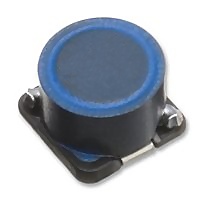
I was prepared for this objection so I have opened one of them and inside there is something similar to the following image.

TDK_SMD_Inductors_Internal

A strong electric field multiplicated by zero (or minimal) magnetic field generates near zero electromagnetic energy.

Magnetic and electric field are not coupled, and they are 90 degree one from the other, so they drains near zero energy from the oscillator and they works very bad as electromagnetic receiver.


Posted: 3/1/2014 5:26:24 PM
dewster

From: Northern NJ, USA

Joined: 2/17/2012

Some stuff I've been working on lately:

Above is a passively shielded antenna made of aluminum tape on 3/8" (~10 mm OD) PEX with a UHF connector.  The front 1/3 area is covered with a 5 mm wide strip which goes to the center conductor, the back half area is covered by a 15 mm wide strip that is grounded.  Very low sensitivity, rather pronounced temperature dependent capacitance, I'm shelving this for now.

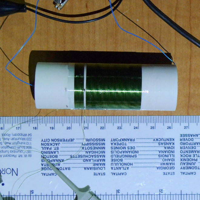
Above is a 0.5 mH coil wound on 3/4" schedule 40 PVC (~26 mm OD) with 34 AWG single coat.  The small winding on the left is the sense coil.  With a large antenna and some capacitive padding (via the RF connector) to bring resonance down within the range of my function generator (2 MHz max), I'm seeing very similar behavior to much larger coils with similar geometry that operate below the AM band (this one would operate above the AM band).  This is encouraging because it allows much smaller enclosures to be used.  Feels like I'm working on a really tiny Theremin in the land of the giants!

Posted: 3/1/2014 5:31:03 PM
dewster

From: Northern NJ, USA

Joined: 2/17/2012

"Our inductor is enclosed completely by a ferrite cylinder. All the magnetic lines are closed inside. So it generates zero (or very minimal) external magnetic field."  - livio

Touche!  But I still think you're wrong about the scale of emissions between the two designs.

And, you know, it's not me that you have to convince that you are correct, it's yourself when you bump up against nature.  I'm just trying to give you a hand.

Posted: 3/1/2014 5:31:49 PM
FredM

From: Eastleigh, Hampshire, U.K. ................................... Fred Mundell. ................................... Electronics Engineer. (Primarily Analogue) .. CV Synths 1974-1980 .. Theremin developer 2007 to present .. soon to be Developing / Trading as WaveCrafter.com . ...................................

Joined: 12/7/2007

"What you (and FredM) are forgetting to consider, is the strong magnetic field produced by the 40 mH coil. " livio

You may be right, livio ... I really dont know. There may well be a strong magnetic field from the inductors..

I never thought that a strong magnetic field from an inductor, and an independant eclectical field from a capacitor plate "antenna", combined to produce an electromagnetic field.. But hey, as I said before, EM is complex...

Perhaps im just too simple to grasp the simplicity of what you are proposing - that one can create EM fields simply by "mixing" magnetic fields and "electric" fields.. Hell, if id realised that before, I could have gone real far in radio! ;-)

Your comments about the charactaristics of electric fields are simply wrong - but hey, again perhaps I misunderstand.. You have personally tested how these fields are blocked by walls, who am I to argue? My expierience of working on a long range capacitive sensor that could search for lost royal treasure under deep wet sand was obviously a delusion, or perhaps the equipment was detecting the same energy that divining rods detect, and had nothing to do with electric fields.. The team looking for the treasure never found it, but they did find a lot of metal junk...

And at the time I was just a junior engineer anyway, I trusted the senior engineers at Avo who were managing the project, but they could have been telling me lies - for all I know they may have been using UFO technology and not electric fields... The 4 insulated sensor pads did look a bit like the landing gear on one of those Roswell craft, and were placed in similar orientation - Hmm... You got me thinking....

No more argument from me - I cannot learn anything from you because, in my opinion, you talk a complete load of nonsense about antennas and fields and EM and simulation and electronics in general,  and have no interest in learning anything - your interest is in promoting the "superiority" of your capsensor - You make bogus claims about things like resolution and stability and radiated energy and all sorts of other stuff, but when these claims are PROVED to be untrue, you still continue making them!

Its all a real shame - you have some great ideas, some beautifully built boards, some extremely clever software, but you are throwing away all your credibility by talking rubbish about matters you dont understand - Talking rubbish is fine, its part of the learning process - its only by talking rubbish that people feel motivated enough to correct you! ;-) .. And its from these corrections that one learns the most - But talking rubbish and ignoring the corrections is utter folly, because you learn nothing and come across as an idiot... Oh, when corrected, one doesnt need to fall over and give up - you can challenge the correction and explore it deeper, and may even prove that you are right - thats all part of evereyones learning process.. But the mistake is to stick to your error because you have invested so much in it that you "cannot" give it up, to look for counter arguments that divert attention away.. Clinging to an error will prove more costly in the end than even writing off years of development that was based on error.

Real sorry.

Fred.
Posted: 3/1/2014 5:32:44 PM
livio

Joined: 2/2/2014

"What you are forgetting to consider is the inductor in your oscillator, which is also emitting an very real electromagnetic field. "

Our inductor is enclosed completely by a ferrite cylinder. All the magnetic lines are closed inside. So it generates zero (or very minimal) external magnetic field.

I was prepared for this objection so today I have opened one of them, and inside there is something similar to the following image.

TDK_SMD_Inductors_Internal

A strong electric field multiplicated by zero (or minimal) magnetic field generates near zero electromagnetic energy.

Magnetic and electric field are not coupled, and they are 90 degree one from the other, so they drains near zero energy from the oscillator and they works very bad as magnetic field receiver.


Posted: 3/1/2014 5:41:35 PM
livio

Joined: 2/2/2014

And does not matter if the inductors are at 90 degree from the rod. The only differences will be in the shape of the radiating patterns.

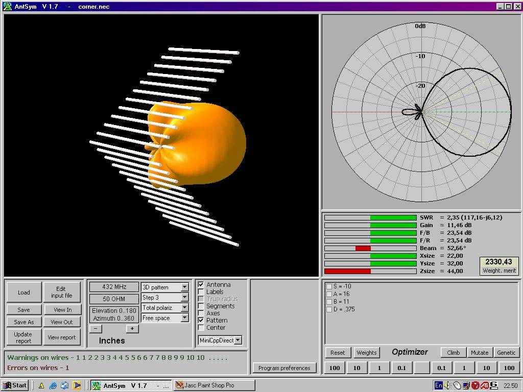
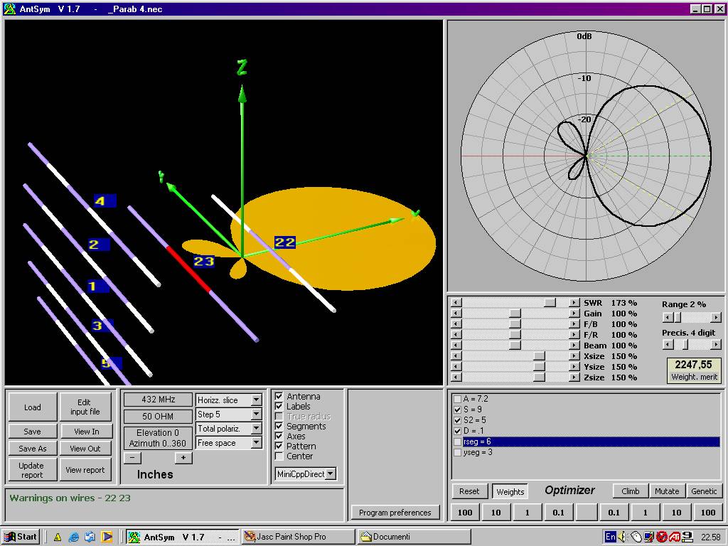
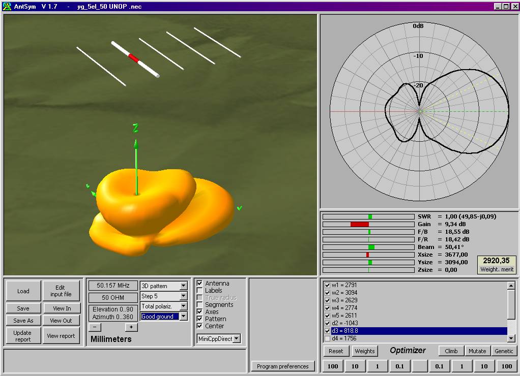
Examples of 3D simulated radiating patterns generated from my AntSym application (made by me in the 2002):

 AntSym1.jpg

AntSym3

AntSym5

AntSym_Splash

I know what I say.

Posted: 3/1/2014 5:48:52 PM
FredM

From: Eastleigh, Hampshire, U.K. ................................... Fred Mundell. ................................... Electronics Engineer. (Primarily Analogue) .. CV Synths 1974-1980 .. Theremin developer 2007 to present .. soon to be Developing / Trading as WaveCrafter.com . ...................................

Joined: 12/7/2007

Hi Dewster,

That shielded antenna looks quite familiar! ;-)

You do need temperature compensation when using this kind of shielding - I used a stereo jack socket so I could have a thermistor inside the antenna, and sum this into my TC circuit.. I did try making a bi-metal temperature sensing capacitor - im sure this would be feasable and one could have the bi-metal between two plates, so you could get + and - TC you could feed through trimmers and have the antenna independently compensated, but I never got this to work. One theremin I built for passive shielded antenna worked ok with just an on-PCB temp sensor, but others didnt... I also had one with a big inductor in series with the ground shield, this worked well but shielding was only partial, the shielded side was still sensitive but less sensitive than the player side.

That coil looks good, and really small - Be real interesting to see the finished theremin!

Fred.

Posted: 3/1/2014 6:02:30 PM
dewster

From: Northern NJ, USA

Joined: 2/17/2012

"I know what I say."  - livio

livio, perhaps it's time for you to start your own thread about your capacitance sensor here at TW?  It's been quite instructive discussing various things with you and for that I'm quite appreciative, but I'm starting to feel that your work is taking over my thread.

Posted: 3/1/2014 6:03:07 PM
livio

Joined: 2/2/2014

" - your interest is in promoting the "superiority" of your capsensor - "

My interest is to explain these things (even to myself). Before this wonderful discussion, many details were overtones for me but I had not really analyzed. Now thanks to you and dewster, we have made many improvements both in the understanding of the theory that in the firmware. For example, without you we would never have discovered the "dynamic resolution" that has allowed us to lower the latency up to 0.8 mS for maintaining a very high resolution for applications that need it.

I'm really sorry that you think that of me, not knowing of course you can think ... in time you will know me and you'll see that there is no person less "commercial". I hate everything that has to do with the money, sell, promotions and products. Ours is not a "product" is only passion for electronics.

Posted: 3/1/2014 6:12:13 PM
livio

Joined: 2/2/2014

"You do need temperature compensation when using this kind of shielding."

We have no temperature problems because we do not amplify them with heterodyning (heterodyning it amplifies by 4 to 8 bit - about 100 times the oscillator defects and the temperature dpendences)

"That coil looks good, and really small - Be real interesting to see the finished theremin!"

Here you can see the new versions with the large area antannas:
http://www.theremino.com/files/Theremin_3D_16.jpg
http://www.theremino.com/files/Theremin_3D_17.jpg

And here some old versions played badly by me:
YouTube video

Please, remember, we do not sell anything, just explain, how to do.


"livio, perhaps it's time for you to start your own thread about your capacitance sensor here at TW?  It's been quite instructive discussing various things with you and for that I'm quite appreciative, but I'm starting to feel that your work is taking over my thread."

Excuse me, however I have written all I had to write, and I am convinced that the solutions that I have indicated, can also be useful for your FPGA version... 

Now I take off my subscription to avoid falling into temptation, if you need something, you can find me on Theremino blog.

You must be logged in to post a reply. Please log in or register for a new account.