Let's Design and Build a (mostly) Digital Theremin!

Posted: 3/4/2014 9:53:01 PM
dewster

From: Northern NJ, USA

Joined: 2/17/2012

ROD vs DISC Theremin "Antennas"

At livio's prodding, I spend a few days looking for good papers on the capacitance of discs.  A good one is "The circular disk parallel plate capacitor" by G. T. Carlson and B. L. Illman, American Journal of Physics, 1994.  In it they solve exactly for parallel plate disc capacitance and present some tabular results.

The capacitance between two closely spaced circular disks of equal radius is (this only holds for very close spacing):

  Cgeom = E0 * A / d

Capacitance of a single isolated disk in space (to ground) is:

  Csingle = 8 * E0 * r

Capacitance between two disks an infinite distance apart is half this:

  Cdouble = 4 * E0 * r

The last equation makes sense because each disc "sees" the universe through it own capacitor, so these two capacitors in series at the measurement point will be half the value due to the way series capacitor values add.

As discussed in other papers, one can use these as boundary conditions for near and far capacitance.

The simple combination of Cgeom + Cdouble = C2 surprisingly gives a reasonably accurate result (<5% error) when compared to the exact tabulated capacitance.

By this line of reasoning, Cgeom + Csingle = C1 may give a reasonably accurate result of the capacitance of a single disc to ground when approached by a second grounded plate of equal radius?  It would be nice to have real data for this, particularly how it related to a disk and a hand, and I may gather some at some point.

Anyway, I put the data in a spreadsheet and compared the single disk being approached by another grounded disk (the C1 equation above) to my rod antenna equation.  Here is the result:

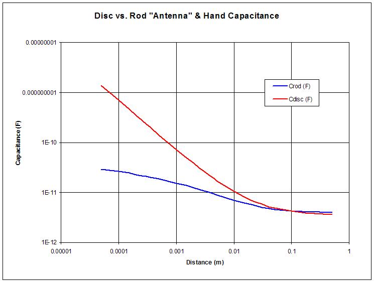
Rod is 250mm long by 10mm diameter.  Disc is 100mm diameter.

Note that the axes are log-log, so the distance isn't linear.  The area if interest for Theremin playing is arguably between 0.1m and 1m, and the disc does seem to have a bit of a sensitivity advantage here.  The disc would be more directional as well. 

This is preliminary, and based on my ad-hoc disc formula which may not be super accurate.  But at this point I'm not entirely convinced that going with a disc pitch antenna is the best, particularly given the vertical rod geometry of virtually every Theremin to date.  But I will make a disc antenna and try it out once I have a prototype up and running again.

The capacitance & change above (disc or rod) is really pitiful!  Kind of hard to believe any Theremin can use that to precisely control pitch!  The square root of it no less!  This aspect of the Theremin constantly amazes me.

[EDIT] Here's a better view of the area of interest:

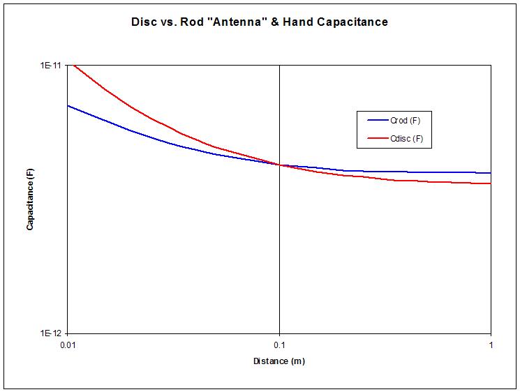
The disc does have a sensitivity advantage.  I'm concerned that the player would find it difficult to carefully orient his/her hand vertically (as well as horizontally, which is required for the standard rod shape).

Posted: 3/4/2014 10:06:55 PM
FredM

From: Eastleigh, Hampshire, U.K. ................................... Fred Mundell. ................................... Electronics Engineer. (Primarily Analogue) .. CV Synths 1974-1980 .. Theremin developer 2007 to present .. soon to be Developing / Trading as WaveCrafter.com . ...................................

Joined: 12/7/2007

Dewster,

Just looking at the graphs, not the maths, it appears to me that these back up my expierience with plate antennas in general..

There is a much more rapid increase in capacitance as the hand approaches the plate when closer than 10cm than what one gets from a rod sensor (antenna), and certainly for a heterodyning theremin this is the last thing one wants, as it compresses the octaves / notes at the high end even more.

Yes - sensitivity is increased close to the plate - but I cannot see any situation where this is desirable.. One wants sensitivity increased as one gets furher from the sensor, or increased / adjusted generally - but certainly not a sensitivity increase close to the sensor without at least an equivalent increase further from the antenna.

This is an argument which raged at Levnet some years ago if I remember correctly - A proponent of Art Harrisons plate theremins saying they were better than rod theremins, and the concensus if I remember correctly was that thereminists who had played plate theremins didnt like them, and engineers believed they must be less linear than rod theremins.

Apart from the maths which only looks at the plates with respect to each other, there is also the distributed capacitance due to the players body parts which I think contribute to linearizing the capacitive fields when (particularly a long) rod is used - none of these geometric effects are present with a (particularly small) plate AFAICS..

From a geometric perspective, having a rod which was wider at the top, oe connected to a plate at the top, could I think improve linearity - I think livio mentioned a 'leaf shape' antenna, and a shaped antenna could work - But I think that the plane that the hand moves on needs to be towards a smaller area portion of the sensor, with the wider area being out of the direct focus.

I am sure that a rod antenna curved towards the player above them does improve linearity - such an antenna could be shaped to give near perfect linearity for a given player in a given environment, but its not really practical.. ;-)

Fred.

Pictures of arm / rod capacitance relationships:

http://www.thereminworld.com/files/photos/14665/couplings2.jpg

http://www.thereminworld.com/files/photos/14665/couplings.jpg


Posted: 3/4/2014 11:05:03 PM
dewster

From: Northern NJ, USA

Joined: 2/17/2012

"This is an argument which raged at Levnet some years ago if I remember correctly - A proponent of Art Harrisons plate theremins saying they were better than rod theremins, and the concensus if I remember correctly was that thereminists who had played plate theremins didnt like them, and engineers believed they must be less linear than rod theremins."  - FredM

Yes, playability from two angles is impacted negatively for the canonical heterodyning Theremin with a plate pitch antenna: 1) linearity near the antenna goes completely to hell, and 2) there is an axis of precision with respect to the pitch hand that the player must deal with after perhaps spending years developing a technique that had no concern with this.

In a digital Theremin 1) could perhaps be dealt with via linearizing functions, and 2) could likely be ameliorated by using a larger diameter disc, which would likely further increase overall sensitivity.

Disc antennas seem like a dead end for conventional Theremins, but they perhaps warrant more investigation for digital Theremins.  I added another chart above which shows the area of interest better.

One might get an inherently more linear response and decent sensitivity/playability by using a rectangular plate, say 50mm wide by 250mm high.  This would provide some directionality as well. 

My spreadsheet formulas don't currently have the option for differing size hand and antenna, assuming they are the same - I don't feel comfortable speculating farther without fitting things to real data.  But a whopping huge disk approached by a small grounded hand might not look nearly as bad as the simulation results above.

Posted: 3/5/2014 1:04:31 AM
FredM

From: Eastleigh, Hampshire, U.K. ................................... Fred Mundell. ................................... Electronics Engineer. (Primarily Analogue) .. CV Synths 1974-1980 .. Theremin developer 2007 to present .. soon to be Developing / Trading as WaveCrafter.com . ...................................

Joined: 12/7/2007

" But a whopping huge disk approached by a small grounded hand might not look nearly as bad as the simulation results above." - Dewster

I agree - I think a whopping disk or plate could actually be quite usable even with a heterodyning theremin without linearization...

But it comes with a price - a whopping background capacitance!

And I gotta ask the question - Why ?  To me we are getting into the territory of "universal"  capacitive sensors rather than a sensor for the specific application of the theremin.. And if thats the direction, fine - I think its probably a better direction to go from a commercial perspective - Intruder alarms, interactive sculptures, musical matresses ;-) - applications are only limited by ones imagination.. And almost all applications are less demanding than the theremin application.

But when looking at the theremin, there would need to be a damn good reason IMO to justify departing from the rod and loop - it just wouldnt make any commercial sense otherwise.

So if one came up with a different antenna or sensor which really solved some theremin problem in a way that would be obviously attractive to a good percentage of any potential market, then it may be worth taking the risk, but IMO if it doesnt do this, then moving from the rod and loop to something else, even if this had some technical advantage, would be folly.

Says me who is dumping the rod (and possibly the loop) and the whole "no touch space field wave your arms about" theremin concept and making a theremin with a  capacitive ribbon controller ;-).

But in so doing I am effectively binning the theremin and creating a 'new' instrument based on its principles.. If you are making a theremin, it needs a rod and loop!

Fred.

Posted: 3/5/2014 7:43:06 AM
livio

Joined: 2/2/2014

These objections are not new, and I have always ready my 50 x 50 cm "antenna", to demonstrate this: Connecting with a crocodile, the large antenna to my little Theremin, the graph line follows my hand at two meters away. Then disconnecting the big antenna you are unable to reach half a meter.

The physical laws give us only this microscopic chance of improvement and, having nothing better, I think it's fair to take advantage of it. All the talks about linearity does not matter, if you can do two or three multiplications necessary to linearize.

Why instead doing many calculations, you give a try to my oscillator with a 200 cm² plate?

This way, your maximum distance could increase of at least 50 cm, at parity of all other conditions. We are not asking for more, these additional, 50 cm are enough for us. And at the end you would have an oscillator simple, small, easy to build, sturdy and with excellent temperature stability. Problem solved and move on to the next stage.

Posted: 3/5/2014 8:05:27 AM
livio

Joined: 2/2/2014

Even a car could be built with tubes and rods, but a Ferrari is more beautiful and even works a bit better. The new antennas are insulated with Kapton up to 50kV, work a little better than rods and are even beautiful.

Theremin_35b

Theremin_23c

This is not a "concept". Lello built (3D-printed) several of these Theremins (each one with a new and better shape) and they are used every day by musicians, in piano bars and on cruise ships.

Posted: 3/5/2014 3:56:55 PM
dewster

From: Northern NJ, USA

Joined: 2/17/2012

"The most critical point is that the oscillator must have an incredibly low noise."  - livio

Can you offer some evidence to support this statement?  I understand how noise is generally a bad thing, but sometimes it is benign (if it can be easily filtered to the point where it isn't a problem), and sometimes it is introduced on purpose to cure something else.  My NCO uses dither to reduce spurious emissions and sticky points, and the sensing side benefits from the dither as well because it increases resolution below the digital limit.

For all I know I'll end up using your oscillator, but I need good engineering reasons to do so.

I haven't studied them much, but one thing that bothers me about single transistor oscillators is the dynamic capacitance of the active element.  Another thing is the phase relationships that can lead to stalling in certain scenarios.  A third thing is the difficulty of implementing ESD protection.

"But when looking at the theremin, there would need to be a damn good reason IMO to justify departing from the rod and loop - it just wouldnt make any commercial sense otherwise."  - FredM

I pretty much feel this way too.  Though livio's pics are quite pretty and seem like the result could be fairly functional.  Maybe a paddle for the pitch antenna and a traditional loop for the volume?

"The physical laws give us only this microscopic chance of improvement and, having nothing better, I think it's fair to take advantage of it. All the talks about linearity does not matter, if you can do two or three multiplications necessary to linearize.

Why instead doing many calculations, you give a try to my oscillator with a 200 cm² plate?"  - livio

What you say makes sense, and I do intend to give it a try!

Posted: 3/5/2014 8:12:36 PM
livio

Joined: 2/2/2014

1) evidence to support this statement?  I understand how noise is generally a bad thing...
2) the dynamic capacitance of the active element. 
3) phase relationships that can lead to stalling in certain scenarios. 
4) difficulty of implementing ESD protection.

These are four important questions, and I have good answers, that will take away all doubt. But today, has been a difficult day (we are implementing two new type of PIN, one for the stepper motors and the other for the PWM, implemented through NCO) and I no longer have the energy, to respond with the required accuracy. Now I have to prepare a bit of food and then going to sleep, for me now it's almost 21.

Posted: 3/6/2014 1:19:53 AM
dewster

From: Northern NJ, USA

Joined: 2/17/2012

livio, take your time, no need to hurry.

================

I think you're throwing away ~1/2 of the sensitivity in your circuit:

I'd probably use a larger value for C1, like 100pF or more.

Posted: 3/6/2014 9:15:43 AM
livio

Joined: 2/2/2014

"'I'd probably use a larger value for C1, like 100pF or more."

You should take into account, that in series with C1, there is the antenna capacitance, which in this scheme is 10 pF, but that in our 100 to 200 square centimeters standard antennas, is much less. Please note, that our antennas have 90% of the area away from the body of the instrument, to decrease their capacity and that instead, the EW Classic antennas, have a good 20% of the area, close to the metal parts of the instrument.

Therefore, a Theremin has little to gain, if you increase this capacitor to 100pF or more.

In the CapSensor we already put a​ very large one (18 pF), to allow maximum sensitivity, even with very large antennas and while working very closely. But in a Theremin would be good to reduce it, to increase the linearity, to avoid too large frequency variations, when the whole hand is in contact with the antenna and to increase the resistance to ESD events.

So, in a Theremin with our antennas is better to reduce it to 5 pF, and that's what we do in Lello's theremin with a 10 pF capacitor in series (a radial capacitor with 20 KV isolation).

I forgot to say... you also have to take into account that not all of the C2 10pF are real, because the "G" node has a complex impedance and acts both measuring and driving the oscillating circuit. This configuration also acts as a "Q multiplier" (Q-Multiplier-Example1  Q-Multiplier-Example2) and eliminates, in fact, most of the loads due to the R1 resistance, the magnetic losses in the core and the internal capacity of the coil (those famous 3.5 MHz resonance declared by TDK).

And as we're pretty close, I answer to your point (2) "the dynamic capacitance of the active element". Look at C3 and C4 capacitors, they are larger than the "capacitance of the active element" (static) and huge compared to dynamic capacitance. So the influence of the "dynamic capacitance of the active element" on changes in frequency, is reduced to negligible levels.

These are the reasons why a Colpitts works better than other configurations.

And finally the incredibly low noise of 0.8 nV/sqHz (nanovolts!) of the BF862, completes the job!

By comparison the 4069 used on OpenThereminUNO has a noise of almost 1 uV (micro-volt, 1000 times greater!), measured by myself. Being 4069 a digital component, noise is not mentioned, nobody cares about digital components noise. Digital components are not designed for a front-end.

No FET has a lower noise than the BF862, the closer is the BF861A with 1.5 nV (the double), moreover the BF862 has also a noise current of about 0.1 femtoAmpere/sqHz (do not even try to make a comparison with the 4069...)

Why do we need a so low noise?
Short answer: "Because the signal to be measured is very low".
Long answer: The next post will explain why your theoretical graphs regarding the area of the antennas, do not correspond to reality (they take in consideration an antenna isolated in space and forget to consider the noise and the static capacitance of the measuring and driving electronic components)


You must be logged in to post a reply. Please log in or register for a new account.