"if you are forced to amplify it via heterodyning, then you will likely be amplifying thermal drift as well. " - Dewster
I dont see this - Apart from if one had two oscillators with different thermal behaviours, otherwise IMO heterodyning can even act to reduce or compensate for thermal drift.
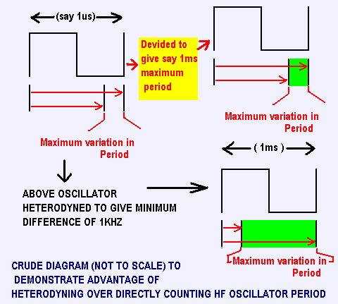
Any form of straight "amplification" (Whether this be heterodyning or extending the period through division) will amplify signal and noise equally, so the SNR wont change, and AFAICS this also applies to thermal error.
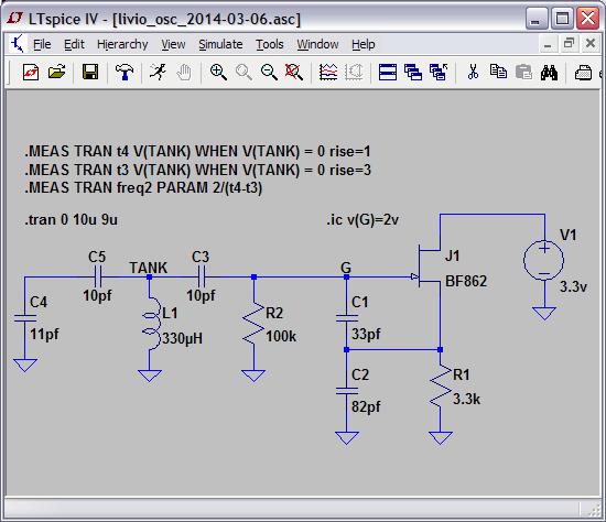
"Please suggest a better solution (with frequencies and component values) and we will test it as soon as possible
(but please, a simple and workable solution, not a theoretical block diagram, perhaps impossible to achieve and ever made by anyone)
(and please, not the OpenTheremin oscillator, with capacitive trimmers and oscillator sensitivity reduced to almost nothing, by parallel capacitors for a total of nearly 150 pF)"
- livio
I dont like this..
This IMO should be an exploration, not a contest, and when asking someone to provide designs, tying their hands behind their back aint helpful - Also, your ideas of "simple" and someone elses are not likely to be the same - to me "simple" is fitting a damn discharge tube, to you its fitting a 20kV capacitor!
Apart from which, Dewster has presented several oscillator designs here which to me look far better suited to digital application than your oscillator - but he is going the route of air coils - and as I understand it you want ready-to-buy Ferrite inductor - This is one of the things which annoys me about "newcomer" theremin designers (and I was the same!) They look at things like air coils and think "i can use a ferrite" but dont ask the simple question "Why did a competent designer use an air coil if a ferrite is just as good".
and please, not the OpenTheremin oscillator, with capacitive trimmers and oscillator sensitivity reduced to almost nothing, by parallel capacitors for a total of nearly 150 pF
The 150pF is there by design! It doesnt "reduce sensitivity" if one is comparing it to the theremino design, because the open.theremin employs heterodyning, and in fact the RESULT of this is GREATER SENSITIVITY than the theremino!
I really dont believe that you are in any position to be critical of anyone elses design because, quite frankly, there is nothing particularly novel or good or clever about the theremino design - the only thing I have seen from you which does look really good is your software, but I havent explored that deeply. Your claims for theremino are what gives it the edge over the open.theremin, but some of these claims (resolution for example) have been shown here to be completely untrue.
I certainly think the open.theremin is capable of FAR higher resolution due to its topology, and MUCH lower latency, than your present theremino can even dream of.
I do however agree with you about capacitive trimmers, and I think the open.theremin oscillator could / should be improved, and that probably a better oscillator for this application could be designed to replace both the theremino and the open design.
As you are both "open" projects, why not collaborate? Get the best of both of your designs and software - I really think that with your software, open.theremins heterodyning topology, and perhaps an oscillator improvement / redesign, some really good digital modular theremin stuff could get to market.
One "problem" is that you are looking at short to-market time scales - This is great in that you actually do get to market.. But to do a GOOD theremin takes much more time than you are giving it - in the case of Dewster and I, years have been devoted - In my case, I could have put many products on the market which were as good as other stuff there but I went too far the other way in seeking perfection -
In order to impact the market, you need something special - You wont get that by rushing - but you can get a bigger impact if you believe things about your product which arent true, and convince others to believe this as well.
If, like me, you arent a salesman - and if you pull your products apart more mercilessly than any competitor or critic ever could, then you aint going to sell anything even if they do get to market - unless you really have something exceptional and believe in it and can convey this.. But getting there takes a long time!
Fred.