Let's Design and Build a (mostly) Digital Theremin!

Posted: 3/11/2014 3:40:27 AM
FredM

From: Eastleigh, Hampshire, U.K. ................................... Fred Mundell. ................................... Electronics Engineer. (Primarily Analogue) .. CV Synths 1974-1980 .. Theremin developer 2007 to present .. soon to be Developing / Trading as WaveCrafter.com . ...................................

Joined: 12/7/2007

"The LVC1404 is made exactly for this" - Dewster

Yes, ive looked at that part before.. It was you who got me looking at CMOS for analogue again, after I had kind of moved to 'standard' linear years ago.. and I must admit ive really fallen back in love with unbuffered CMOS! ;-)

Im not sure about the LVC1404 for the oscillators I want to build - for one thing, its SMD only - then its 3 times the price of an HCU04 (the cost of extra PCB real-estate is offset by the cost of placing a damn SMD - or at least it is for me)..

But the thing that puts me off it more than anything else is that I think the inverters are buffered..

Messing about with 6 UB inverters all operating in their linear zone to some degree, 5 in series to operate as per your "opamp" and one as a seperate 1/3 gain inverting buffer on the input sine, I get a wonderful collection of tappable low-Z waveforms ranging from sine to soft square..

I can add local input resistors and -ve feedback to any of these inverters to spread the effect (distortion) as I choose, provided the overall gain of the 5 is high enough.. Ive been  playing with this kind of stuff for a while now as independent "pre-mixer-processing" - but actually, in my case, if I can incorporate this "processing" in the oscillator itself, I would be simplifying the design and reducing complexity - and I am reasonably sure that I can do this on your oscillator without affecting stability in any way.

This is where I am "deviating" and going off-topic as my main interest isnt digital .. I accept that from a digital perspective, the LVC1404 may be a better choice.. But even here I am not 100% sure.. I just have this "feeling" that your "opamp" with its linear operation, when implemented using unbuffered CMOS rather than "hard switching" buffered devices operating in "logic" mode, will be better and more stable..

But its only a feeling - could be utter BS - and (apart from switching transients and possible threshold noise, which again could be BS) I cannot explain or justify this "feeling".

Fred.

Some pictures just to show the sort of ideas (Simulations only - Dont try to build!)

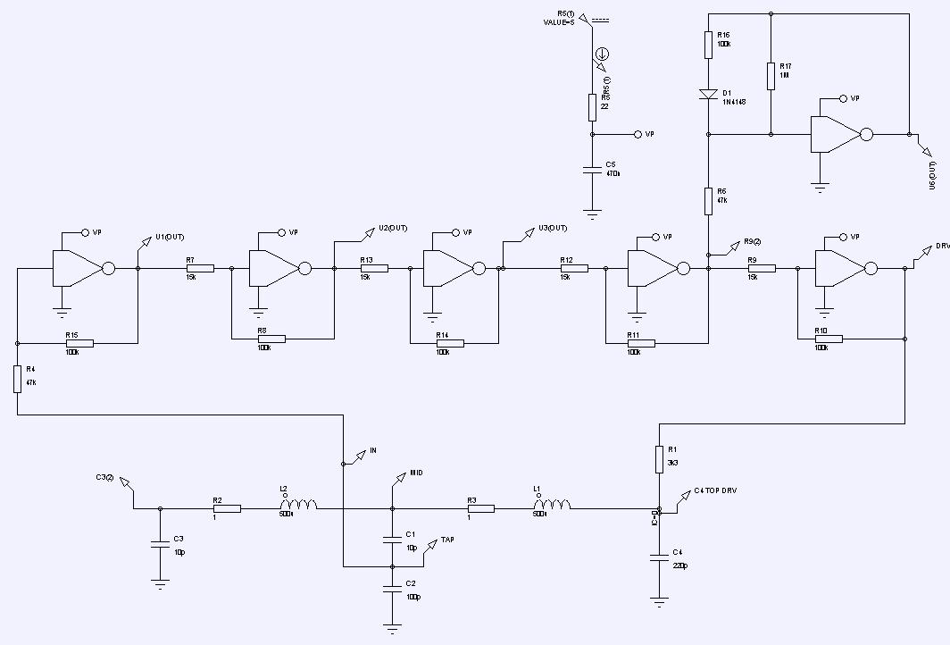
Waveforms available (all buffered, Low Z) include sine, extra odd harmonics (square shaping) Square, extra even harmonics (ramp shaping) - all sorts of simple mixes available:


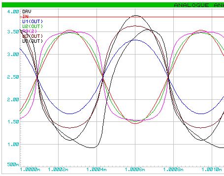
 Without the diode stage, all the waveforms are completely aligned and 'smooth', there are no sharp edges, no current spikes containing excessive harmonics - IMO this points to extremely stable oscillator operation (I am referring to Dewsters original oscillator / + the first CMOS version shown thereof)

The above schematic seperates the gain stages allowing each to be set to taste - this is NOT needed unless you want to use these stages for analogue purposes - For digital operation there is no advantage in using the above schematic..

Posted: 3/11/2014 12:57:21 PM
livio

Joined: 2/2/2014

"Our objectives are different - I dont care if I "waste" a few components - dedicating a whole hex inverter to a single oscillator, and having perhaps a seperate comparator on the output if I want to drive logic, doesnt bother me at all.. I like simple, but opt for more "complex" if "simple" doesnt give me everything that im after." - FredM

I'm sorry, I have explained myself badly. My reduce to a minimum the component count, is absolutely not to save money, but to maximize performances. I'll give you a few examples: 

1) The versions with dual inductor have a sensitivity lower than those with single inductor. Dewster also confirmed this. 

2) The greater the number of components and the PCB becomes more great. This inevitably increases the length of the links and then the parasitic capacitances. 

3) A large PCB extends with temperature and produces frequency drifts, caused by occasional mechanical settlings of the components. 

4) Add unnecessary components can produce additionals drifts of capacity with temperature and worsen the stability. 

5) Large components capture more 50Hz noise from the mains. 

This list could be continued, but I prefer not to be boring.


"this is one of the primary mechanisms by which a FET is destroyed! - Its not capable of surviving high gate currents, and will be damaged and its performance permanently degraded  even if the part isnt completely destroyed." FredM

In our CapSensors the double "T" formed by the input capacitor, the grounded inductor the second capacitor and the gate shunting capacitors, completely eliminate this problem. 

With the new Dewster versions, who do not have the grounded inductor, probably we will add a Gate resistor and two diodes. I am studying the problem. There are many simple solutions, also without unusual components, as gas dischargers (too much high discharge voltages) or Littlefuse TVS diodes (they could cause inacceptable degradations of the performances)

In every case the antenna must not be metallic and connected directly (galvanically) to the active components. An input isolating capacitor is imperative! I could burn an OpenThereminUno with less than 19 Volts, with my laboratory power supply!


"SN74LVC1404 - OSCILLATOR DRIVER - FOR CRYSTAL OSCILLATOR OR CERAMIC RESONATOR"

We are not making a crystal oscillator but a VFO. And not a normal VFO, but an incredibly silent VFO that must compete with so little signals...

I have measured now the frequency changes produced by a hand at 1 meter. (This is not to work at 1 meter but to guarantee an absolute stability at 50 cm)

My test says that at the distance of 1 meter and to make a change of 1 Hz, a hand must move approximately 2cm (with a CapSensor standard working approximately at 2.5 Mhz and with a antenna of 130 cm2) 

A 2cm movement is approximatively 2 semitones if using 8 octaves (96 notes) on a 100 cm range. To play minimally stable notes I calculate a max noise of 0.1 Hz (20% of a semitone). 

So we must make a VFO oscillating at 2.5 MHz with frequency noise less then 0.1 Hz. This is about 100 times best, of the best VFO for decoding the SSB, that are the best variable oscillators in the electronic world. (we are speaking about VFO, Variable Frequency Oscillators, not Crystal stabilized oscillators)


How to measure the frequency instability (noise) of the oscillators

To test if a 4069 or a LVC1404 can produce the required frequency stability (noise) of 0.1 Hz (on 2.5 Mhz) or 0.01 Hz (on 300 KHz) you can do this:

- Remove the antenna and substitute it with an equivalent (10 or 15 pF) capacitor. The precise capacity is not important.

- Place the oscillator and the equivalent capacitor, in a grounded metallic box, to minimize environmental induced noises.

- Use a frequency meter capable of multi period measurements and set it for a integration time (multi period) of about 10 to 100 milli Seconds.

- Set the instrument to convert the value to frequency and list values to a file.

- The listed values must be stable (in the short time - not temperature variations) better than 0.04 parts over a million. Very, very hard to obtain this.

Here you can see that we tested CMOS gates (and operationals) for long time, before to decide that FETs are better: http://www.youtube.com/watch?v=duaSGuiM4bM

Posted: 3/11/2014 2:39:03 PM
livio

Joined: 2/2/2014

"One thing that slightly bugs me about single FET oscillators is that they run class A.  Which means they aren't the most power efficient. Which means they have to heat up a bit before they're stable." - dewster

These oscillators are influenced very little by the temperature of the FET (due to the large capacitor between gate and source which minimizes the capacity variations). We are speaking about few milli Watts, and so small power can produce very small changes in temperature, much smaller than the continuous change due to the air movements. But also considerable variations in ambient temperature does not cause problems if you use these oscillators. I can continue to play quietly while a colleague of mine waving an hot hair drier on CapSensor naked, out of the container! Try doing that with an EW ...

"Do you know of a thru-hole device I could use in my breadboard that would be similar to the BF862?" - dewster

You could solder three wires to the BF862 makes it easy to use SMD if you have the right glasses and a small soldering iron, as shown here: http://www.theremino.com/en/technical/tables-and-notes/#smdcomponents

But better yet, I would recommend you make tiny circuits by connecting components directly together with small wires or copper adhesive tape on vetronite, cutted with scissors. On a breadbord these circuits may not work well.

Then I would recommend you make a order from Mouser to: 

- 10 BF862 ($ 3)

- 10 TDK inductors ($ 5)

- 20 SMD capacitors NPO, for each common value from 1 pF to 100 pF ($ 5)

- 20 SMD resistors 0805 for each most used value ($ 5)

- 20 diodes 1N4148 (we will use them for ESD Protection) ($1.2)

- 10 SMD transistors BC846 (for the isolating stage, refer to the CapSensor schematics) ($ 0.6)

Probably all this, will not cost you more than $ 20, if you make the order we could pay it (via PayPal please) using the donation cash for the research. We are happy to do researches and we hope you could, in the future, no hurry for this, make also a modular device that connects with our system.

When the projects are pretty definitive, we could also send to you some little PCB for test oscillators, made by me, with the mill machine.

Posted: 3/11/2014 3:02:49 PM
dewster

From: Northern NJ, USA

Joined: 2/17/2012

"Yes, ive looked at that part before.. It was you who got me looking at CMOS for analogue again, after I had kind of moved to 'standard' linear years ago.. and I must admit ive really fallen back in love with unbuffered CMOS! ;-)"  - FredM

There's a lot to love there!  Probably more the way I learned than anything else, but I feel more at home doing push-pull stuff than single-ended.

"My reduce to a minimum the component count, is absolutely not to save money, but to maximize performances. I'll give you a few examples:"  - livio

Good points and I agree with them.

"The listed values must be stable (in the short time - not temperature variations) better than 0.04 parts over a million. Very, very hard to obtain this."  - livio

Interesting calculations.  It's nailing these kinds of things down that digital Theremin research needs.

===============

This morning I came downstairs and turned on the WISC FET oscillator running at 2.68 MHz with a hand-wound 0.5mH air coil and 250mm antenna. 

Setting the scope trigger delay to 50ms (max on my old scope) and zooming up 50ns/division (to easily see a wave) I didn't see any significant noise or instability until I turned my PC on, which is ~1M away.  I believe with this method of observing noise you don't need to consider the operating frequency, and can take the ratio of the noise amplitude to the total measurement period.  50ns/50ms=1ppm, and I was seeing quite a bit less than this, maybe 1/10 or less, so 0.1ppm. 

And this is with an antenna and simple air core coil, no shielding of any sort (plastic box and wires everywhere).  I'm powering the oscillator with a 9V battery and LDO 3.3V voltage regulator (LP2950-33LPRE3 from TI).

I'll try to make a counter-wound coil today and test that out with my PC turned off, and will look at noise with a capacitor as well.  I'm finding my nearby PC is a huge source of interference.  And my oscillators always glitch on the scope when the washing machine or boiler in the other room cycles on/off.

My feeling is environmental noise will be generally be way higher than the intrinsic noise of this oscillator, so the job shifts to lowering that.  I haven't seen the series capacitor trick lowering noise, but this might be because the antenna point is so high impedance?  If anything, the series capacitor seems to increases noise, but that could be wrong as I'm starting to go blind squinting at my tiny scope screen from across the room. ;-)

Posted: 3/11/2014 3:17:51 PM
FredM

From: Eastleigh, Hampshire, U.K. ................................... Fred Mundell. ................................... Electronics Engineer. (Primarily Analogue) .. CV Synths 1974-1980 .. Theremin developer 2007 to present .. soon to be Developing / Trading as WaveCrafter.com . ...................................

Joined: 12/7/2007

" There are many simple solutions, also without unusual components, as gas dischargers (too much high discharge voltages) or Littlefuse TVS diodes (they could cause inacceptable degradations of the performances)" - livio

Livio, im going now - I dont want to engage in this kind of "debate" with you, because its pointless.. Everything which is proposed or suggested is countered by you with some pointless bogus argument - For example your "gas dischargers (too much high discharge voltages)" - When one deliberately has high voltages on the antenna, you NEED discharge devices with firing voltage in excess of the antenna voltage! - then the "Littlefuse TVS diodes (they could cause inacceptable degradations of the performances)"" But you propose no mechanisms to explain your statements!

You talk about using clamping diodes and these are often fine - but they too can introduce problems (voltage dependent capacitance) particularly if you dont have a at-antenna discharge tube and therefore must deal with the full ESD potential / current rather than the hugely reduced (/100 or more) potentials after the discharge tube has done its work.

You see, this is the problem - let me lay it on the line one more time before I go - You make statements of "facts" which are not facts! - You may be right about some of what you say, but stop presenting your GUESSES as if they are verified facts! You have stuck with EVERY false idea that you came here with, despite many of these being proved to be false.. This makes discussion with you pointless IMO.

The way I learn here is by being shown my mistakes or better ways to do things, and adopting these - If I cannot agree with something, I present my case with as full reasoning as I can manage, for a dual purpose - A) It makes it easier for an "opponent" to identify the error/s in my thinking OR B) it makes it easier for the "opponent" to see the error in their thinking.

The above process doesnt happen between you and me.

Fred.

Posted: 3/11/2014 3:58:13 PM
dewster

From: Northern NJ, USA

Joined: 2/17/2012

"Then I would recommend you make a order from Mouser to: 

- 10 BF862 ($ 3)

- 10 TDK inductors ($ 5)"  - livio

Thank you for the offer!  I have some more experimenting to do before I make an order, particularly for inductors. 

The smaller tank capacitance of the WISC FET design places higher performance demands on the tank inductor.  Those TDK inductors are very close to not functioning.  For instance, an ideal 330uH inductor would resonate at 2.8MHz with a 10pF antenna.  With a 5pF antenna it would resonate at 3.9MHz.  The 330uH TDK inductor has a minimum self resonant frequency of 3.5MHz.  You might have to use two or more smaller values in series.

That, and as we have discussed, the TDK parts have a temperature dependence of 162.5ppm/C.  I haven't seen any VFO oscillator designs that use ferrite cores, they are seem to be all air-core.  Of course they are operating at frequencies where ferrite isn't necessary to make a small coil.  I presume the air core in a VFO could pick up RF interference, even inside of a metal box, though they are usually wound torroidally which would tend to minimize this.

==========

I ran across "spider web" coils the other day:

Used in RF.  Often wound with litz wire.  I believe they have low self-capacitance and high Q.  The windings go from the inner diameter to the outer, so it isn't a torridal form or anything.  So I assume they pick up environmental RF like crazy.

==========

livio, have you seen this paper (I pointed to this earlier in the thread)?:

http://ecad.tu-sofia.bg/et/2008/ET2008_Book1/Electronic%20Medical%20Equipment/25-Paper-T_Neycheva1.pdf

And here is my Excel spreadsheet simulation of it (ditto):

http://www.mediafire.com/?wcln9pdeqn4ehkc

Dealing with 50/60Hz hum may be necessary in hardware/software.  I believe future digital Theremins and associated environmental capacitance sensors will use full-blown adaptive filters to reduce environmental noise.

Posted: 3/11/2014 4:13:32 PM
FredM

From: Eastleigh, Hampshire, U.K. ................................... Fred Mundell. ................................... Electronics Engineer. (Primarily Analogue) .. CV Synths 1974-1980 .. Theremin developer 2007 to present .. soon to be Developing / Trading as WaveCrafter.com . ...................................

Joined: 12/7/2007

"There's a lot to love there!  Probably more the way I learned than anything else, but I feel more at home doing push-pull stuff than single-ended." - Dewster

Yeah - I understand that.. And there are advantages / disadvantages to both, choice is application specific and often not clear.

http://www.ti.com/lit/an/scha004/scha004.pdf (details of buffered vs unbuffered)

The variation of input capacitance as a function of Vin and supply voltage is a reason I think unbuffered CMOS in a linear feedback circuit MIGHT be better than buffered CMOS - This is probably counter-intuitive (and I may be completely wrong) because Cin variation is far greater with unbuffered than buffered - But my feeling is that in a closed loop, capacitance change will be "compensated" better than with buffered parts where it will affect the switching thresholds.

Fred.


Posted: 3/11/2014 4:30:15 PM
livio

Joined: 2/2/2014

"The smaller tank capacitance of the WISC FET design places higher performance demands on the tank inductor.  Those TDK inductors are very close to not functioning.  For instance, an ideal 330uH inductor would resonate at 2.8MHz with a 10pF antenna.  With a 5pF antenna it would resonate at 3.9MHz.  The 330uH TDK inductor has a minimum self resonant frequency of 3.5MHz.  You might have to use two or more in series." - dewster

I have not tested them in your serial configuration but in our CapSensors they are working fine. I will do simulations and tests about this.

[EDIT 1] Do you remember that inductor must be completely magnetically shielded? Large inductors will be very difficult to shield. Maybe there are more large TDK inductors with best charachteristics to choose.

"have you seen this paper (I pointed to this earlier in the thread)?" - dewster

IMO it is best to remove low frequencies immediately.

Maybe if you prefer we can increase the input capacitor to 100 pF (so we loose sensivity from 4.3%F/pF to 4.0%F/pF - in your last circuit - simulations here)

Or maybe we could increase it also to 330pF loosing about nothing in sensitivity.

Also a 100 pF has a very high attenuation to the 50 or 60 Hz frequencies. Without this capacitor you must combat the induced felds increasing the antenna voltage. But the antenna voltage can be increased only to a maximum of 250 volt with an increment of 10 times, reducing the external interferences by not more than 20 dB.

Instead a 100 pF capacitor reduces low frequency external fields by 120dB (1KHz) and 170 dB (50 Hz), there is a file in the simulations to test this "InputCapAttenuation.asc"


Posted: 3/11/2014 4:46:29 PM
livio

Joined: 2/2/2014

FredM,
please, let us design these oscillators without burning them, every day, with your lightnings.

When it will be finished, every one of us will be able to add any additional device, discharge tubes, temperature and atmospheric pressure corrections, heterodyning... But before we must try to make a heart with good features.

[EDIT 1] If the word FET bothering you a lot, you can use a transistor in place. You could also use the same transistor that uses EW, but I'd recommend using low noise transistors. 

Simulation here: http://www.theremino.com/files/DewsterV3_Transistor.asc

The characteristics are the same as the version of dewster with BF862, the only difference will be a slightly lower stability with temperature and a slightly higher noise.

In this simulation I put a 330 pF input capacitor which ensures the elimination of 160dB 50Hz and reduce the sensitivity only of a tiny fraction. 

  • DewsterV3 without input cap = 4.34% F/pF 
  • This version with 330 pF = 4.22% F/pF
Posted: 3/11/2014 6:08:51 PM
dewster

From: Northern NJ, USA

Joined: 2/17/2012

I just realized that scope trigger delay of 50ms = 3 /60Hz!  This integrates the 60Hz noise away completely. 

So I set the trigger delay  to 2.5/60Hz = 41.66ms and am seeing about 50ns of variation with a 5pF capacitor in place of the antenna.  The coil, and possibly everything else connected to the oscillator, is picking up 60Hz.  First order of the day then is to construct a counter-wound coil and give that a go.

==========

Looking at some VFO circuits, many include a diode from ground to gate in order to control amplitude.  This might be able to do double duty in helping with ESD.

You must be logged in to post a reply. Please log in or register for a new account.