Let's Design and Build a (mostly) Digital Theremin!

Posted: 3/14/2014 1:10:14 AM
FredM

From: Eastleigh, Hampshire, U.K. ................................... Fred Mundell. ................................... Electronics Engineer. (Primarily Analogue) .. CV Synths 1974-1980 .. Theremin developer 2007 to present .. soon to be Developing / Trading as WaveCrafter.com . ...................................

Joined: 12/7/2007

Great! Now your on the road to multiple circuit destructions, lol ;-)

Oh, just thinking about what I said above regarding capacitor and HBM etc, I think it could be wrong..

A person is going to charge to whatever ES potential they develop, and their capacitance of ~100pF holds this charge, and when they get close enough to a discharge route, this charge will pass via that route via ~1k5R body resistance..

So having a 100pF capacitor to the HV end, with 1k5 to the probe, should behave quite similarly to the HBM - as the probe approaches the UUT, discharge will occur at a proximity determined by the PD..

So a simple piezo charging mechanism with the above should do the job.

Begs the question why simple low cost ESD guns based on something like this dont seem to be available - my friends gun is a low-end device and cost him about £300 second hand!

"Could stick a 1.5k resistor in the sparky end which is hollow and has a tiny spring.  Neat!"

Dont forget that without a capacitor on the output, the charge generated by the piezo has a lot less power, so adding any series element that reduces the delivered 'punch' may not be a severe enough test. I think that from a piezo one probably gets a much shorter pulse, ok the instant it fires you may deliver a higher current spike, but this will probably extremely short in duration compared to what one gets from a charged 100pF.

Also, I think you do need to connect the ground for any realism.

Fred.

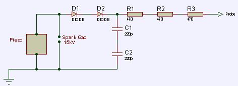
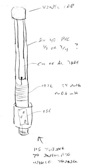
Quick sketchup of what I plan to build one day - all components rated 10kV min, piezo is cranked until one sees a spark across the 15kV spark gap which is behind a glass.. (may need a small R between the piezo and the spark gap so that maximum voltage at the gap only occurs when the capacitor is fully charged)

Some useful ESD links:

Complete set of articles on EMC  ESD etc as .pdf http://www.humerboard.at/ftkl/Design_Techniques_For_%20EMC.pdf

http://www.gr.ssr.upm.es/~jambrina/esd/www.borg.com/%257Eeosesd/

This index page links to 7 articles covering the whole subject of ESD.

Posted: 3/14/2014 10:41:41 PM
dewster

From: Northern NJ, USA

Joined: 2/17/2012

Very nice ESD info Fred, thanks!

I see BBQ igniters ("spark generators") on Amazon for really cheap that use a single 1.5V AAA battery:

http://www.amazon.com/03310-Replacement-Charmglow-Charbroil-Brinkmann/dp/B0094BN8C8/

I might order one just to play with it!  Looks like a fun item to have around, a button activated spark dispenser.

Posted: 3/14/2014 11:10:06 PM
dewster

From: Northern NJ, USA

Joined: 2/17/2012

Connector Connundrum

The newest WISC oscillator seems ideally suited to mounting the coil on the antenna, because the antenna side connects directly to it and nothing else, and the other side of the coil is fairly low impedance.  So a single connection like a banana plug or something should work electrically here if not physically. 

Given enough room the entire oscillator + voltage regulator + output buffer could reside inside the base of the antenna.  I'm kind of partial to this because a piece of 1/2" or 3/4" Schedule 40 PVC could have the oscillator inside the base, the coil wound around the outside above the base, and a plate-like antenna made of Al or Cu tape on one side, with the coil and plate antenna covered in heat shrink tubing.  This would form a completely self-contained sensor, and would get the whole shootin' match out of and away from the hot and noisy FPGA / LED environment. 

But it would need three terminals: power, ground, and output.  Any ideas?  I'm sort of against 1/4" TRS but perhaps irrationally so.  Do they make 1/4" TRS where the plug has something like a chassis mount?  Looking for something electrically and mechanically secure that can take some abuse if the Theremin were to topple over on stage and land on the antenna.  (Or maybe I should make it super fragile, have a side business repairing them, and laugh all the way to the bank?)

This new approach has me wondering if I could just stick three of these tuned a bit differently from each other on a box and call it a day?  The Open.Theremin oscillators are like 1 cm apart!  And the Theremino CapSensor has a PIC processor on the same tiny board.

Posted: 3/14/2014 11:41:29 PM
FredM

From: Eastleigh, Hampshire, U.K. ................................... Fred Mundell. ................................... Electronics Engineer. (Primarily Analogue) .. CV Synths 1974-1980 .. Theremin developer 2007 to present .. soon to be Developing / Trading as WaveCrafter.com . ...................................

Joined: 12/7/2007

There are loads of circular locking connectors, I had the same quandry when looking at directional antennas - I settled on stereo jacke in the end but have several I built using these.. It all came down to mechanics in the end - what diameter tubes I could get, what fitted these with least bother - my idea was to delay deciding until everything was proven, then look at getting apropriate mecahanics engineered for best connector (tapping the antenna tube, using tube diameter converters, that sort of thing..

http://www.rapidonline.com/Cables-Connectors/Circular-Locking-Multipole-Connectors-66501

Posted: 3/15/2014 2:51:06 AM
dewster

From: Northern NJ, USA

Joined: 2/17/2012

Wow Fred, no one can say you haven't been there, done that!  You're always 10 steps ahead of me with great info.

These looks intriguing, I was thinking of something like XLR but didn't like the locking thing.  Screw-in is much more secure.

I'm guessing you can't use those chassis connectors (two on the right) together?  That it takes the freely spinning outer shell on the cable part (on the left) to make it work?  Wish I could find a chassis-chassis connection.

Posted: 3/15/2014 5:29:05 PM
FredM

From: Eastleigh, Hampshire, U.K. ................................... Fred Mundell. ................................... Electronics Engineer. (Primarily Analogue) .. CV Synths 1974-1980 .. Theremin developer 2007 to present .. soon to be Developing / Trading as WaveCrafter.com . ...................................

Joined: 12/7/2007

"I'm guessing you can't use those chassis connectors (two on the right) together?  That it takes the freely spinning outer shell on the cable part (on the left) to make it work?" - Dewster

Yeah, your right about that, I havent found a suitable chassis-chassis connector.

I actually linked you to the wrong product though - These are the ones I have used.. The locking "nut" is free, leaving a reasonable section of barrel behind it that one can insert into a tube..

I started by removing the connector (plastic / contacts) section and placing the barrel into my pillar drill, then grinding the raised barrel section (there to prevent the locking nut from escaping) away, so that I could inser this into my Tufnol antenna tube.. But this was just too much effort.. I then simply cut away this section, leaving a shorter length of barrel to insert - this works but one needs to glue it firmly into the antenna, sort out all the wiring etc (solder leads to connector etc) for the antenna, then at the final stage goop a load of epoxy inside the barrel up into the antenna tube and fit the connector.. Remembering to leave enough gap for the locking section to freely rotate.

With the above palarva, one gets a good strong connector - anything less and the first bump and it just breaks off.

I was spending so much time trying to get this right that I stopped and thought - If I get these into production, I can get some hardware made specifically for the job.. and started using jack plugs just so I could get on with what I was good at ;-)

http://cpc.farnell.com/1/1/18160-socket-multipole-4p-psg01590-pro-signal.html

Oh, BTW .. If you use the above, go for more contacts than you need - These low cost connectors are much more secure the more contacts there are, I found a minimum of 4 acceptable, but 3 werent rigid enough, the 6 pin version is great.


Fred.

(I suspect that for your plan, you may need to do something like I did and have an extended width bulge at the bottom of the antenns at accomodate electronics and fit the plug..)

Posted: 3/15/2014 8:47:19 PM
dewster

From: Northern NJ, USA

Joined: 2/17/2012

Thanks so much for that info Fred!  These types of connectors are often used for CB microphones and such I believe.  And yes, if I go this route I'll need a bulged out area, though it could consist of one big bulge.  I'm starting to think incorporating the oscillator is perhaps too much work, though the antenna+coil still might fly.  I don't have to ground the outer section of the UHF connector, letting it float (or bleeding charge off with a large resistance) would keep sensitivity high and temperature dependence to a minimum.  The capacitance of a UHF chassis connector I tested was around 3pF, with a pretty horrid -2000ppm/C temperature dependence!

Interestingly, the threaded end of a UHF connector fits quite tightly into the ID of 1/2" Schedule 40 PVC, but the gender is wrong for chassis connection so it would need a changer, and it is obviously only 2 terminal.  Speaking of UHF connectors, I bought a few bags of rather crappy ones off of eBay, but this site seems to sell really good teflon ones (I have no direct experience with them):

http://www.mgs4u.com/RF-adapters.htm

"I recently joined a local Ham group that meets once a month, told them I wasnt into the stuff in the way they were but was into theremins  - they have been interested and helpful, and there is absolutely no "holding back" of information or ideas... I am looking forward to the next get-together in 3 weeks - even though 99% of what is talked about is either of little interest to me or over my head ;-)"  - FredM

There were a couple of ham sites I hit early on in my Theremin journey that strongly influenced me (and still do when I visit them).  This is one:

http://www.qrp.pops.net/default.asp

He uses and recommends powdered iron toroids for the high Q LC resonant coils in his VFO circuits.  Like the T50-6, which has a tempco of 35ppm/C and is quite inexpensive.  But winding a 0.6mH coil on there would take 387 turns (calculator here: http://toroids.info/T50-6.php) which is more work than I'm willing to do!  Even the honkering T200-6 would take 240 turns.

==========

Ran a quick and somewhat dirty temperature test on the new oscillator today.  Results:

So I'm seeing around +83ppm/C temperature dependence.  Some positive tempco capacitance could largely balance this out I suppose.  But maybe I should be using a larger positive tempco inductor core and try balancing it out with negative tempco caps.  What to do...  The drift could be worse I reckon.

=========

[EDIT] Doing some really rough tempco tests with caps in my junk box.  Thermocouple says the difference between room temperature and my forehead is ~15C, so I'm sticking caps on my LC meter and looking at the measurement before and after holding them to my forehead for 30 seconds.  Seeing a fairly consistent (for the setup) +400 to +500 ppm/C for the green chicklet polyester types.  I'll try sticking one of these in parallel with the smaller caps and redoing the oscillator temp test.

This sort of thing is probably how the Neanderthals designed their Theremins.

Posted: 3/15/2014 11:48:13 PM
FredM

From: Eastleigh, Hampshire, U.K. ................................... Fred Mundell. ................................... Electronics Engineer. (Primarily Analogue) .. CV Synths 1974-1980 .. Theremin developer 2007 to present .. soon to be Developing / Trading as WaveCrafter.com . ...................................

Joined: 12/7/2007

"This sort of thing is probably how the Neanderthals designed their Theremins." - Dewster

You calling Lev a Neanderthal ?  ;-)

I think its probably the sort of thing that was done when theremins were crafted, before the days when one needed to think "high" (or even living) wages for craftsmen and low-cost products for consumers.

Fred.

"The capacitance of a UHF chassis connector I tested was around 3pF, with a pretty horrid -2000ppm/C temperature dependence!"

I am completely shocked by that! Worse than an ESD gun zap!

I never actually though about connectors and their temperature coefficients - this could explain a lot - perhaps the great results I got from some of those crap inductors I used, which I could never repeat, were due to counteracting effects from connectors or other things I never thought to check... ArrrggggH!

Anyway - Confirmation to me that electronic thermal compensation is the only way to go ;-) .. A few thermal sensors, summing amp and frequency control feedback...

Posted: 3/16/2014 7:33:07 PM
dewster

From: Northern NJ, USA

Joined: 2/17/2012

"You calling Lev a Neanderthal ?  ;-)"  - FredM

Oh, no, just kind of funny in a Far Side kind of way to think of cave people at a workbench.  And strange to think electronics technology has only existed for an incredibly short period of time.

"I am completely shocked by that! Worse than an ESD gun zap!"

Read 'em and weep (>10x worse than that):

I should have collected data for temps up to and above room temp, but we keep our upstairs kind of chilly, and I'm kind of lazy.

Still, this is nothing I'd put anywhere near capacitive sensitive stuff.  Unless I shorted the outer conductor to the inner, or maybe let the outer conductor float.

This is a white insulator UHF chassis connector I bought off eBay.  Probably not a teflon insulator type as it was fairly inexpensive.

I'm finding you have to watch everything that can possibly have a temperature dependence like a hawk.  Tried doing tempco on my new oscillator with a yellowish 100pF cap I had in my junk box that had a large positive tempco.  It brought the +83 ppm/C of the frequency down to +32 ppm/C but the curve is now less linear.  It seems positive tempco caps are fairly non-linear with temperature and with frequency.  Negative tempco caps are much more linear and stable, which is yet another reason to use moderately positive tempco powdered iron core coils.

[EDIT] Just tested the split air-core coil I recently wound, it's dead nuts 582.6uH from -13C to +15C.  It seems the +83 ppm/C of the oscillator is likely coming from the FET. 

Anyway, I think there is some value in taking reasonable measures to reduce intrinsic oscillator drift, even if when you hook it up to a real "antenna" it all goes to hell due to environmental factors.  For instance, there's heat generated inside the enclosure which would be nice not to have to worry about too much.

Posted: 3/16/2014 11:06:32 PM
FredM

From: Eastleigh, Hampshire, U.K. ................................... Fred Mundell. ................................... Electronics Engineer. (Primarily Analogue) .. CV Synths 1974-1980 .. Theremin developer 2007 to present .. soon to be Developing / Trading as WaveCrafter.com . ...................................

Joined: 12/7/2007

"  It brought the +83 ppm/C of the frequency down to +32 ppm/C but the curve is now less linear.  It seems positive tempco caps are fairly non-linear with temperature and with frequency." - Dewster

Yes - the linearity of thermal drift is an issue I suppose.. But I have regarded it as a less important matter.. Not sure if im wrong in this assumption.

Using electronic temperature correction (thermistors or junctions to read temperature, and a frequency correction feedback to the oscillator) I havent got linear correction, but have believed that as long as the drift was contained within a reasonable span, this didnt matter - if the null point moves a few cm towards the antenna, or a few cm in the opposite direction, I felt no-one would notice or care.. As long as the drift wasnt enough to be noticed and/or warrant adjustment of the tuning control... It didnt matter if drift was say 1cm for the first 10 degree change then another 1cm for the following 20 degree change..

I am now having to deal with this in a much more critical way on my ribbon - because even the slightest drift becomes noticable if there is a physical / visual ribbon against which pitches are referenced - I went a little OTT on my latest prototype and went for 1m length ribbon covering 6 octaves (1.3cm/st) and keeping the semitones reasonably alligned to the correct positions looks like it may be a problem as temperature changes.. Ok, finger pressure etc makes it less critical - perhaps im worrying too much...

Fred.

You must be logged in to post a reply. Please log in or register for a new account.