Let's Design and Build a (mostly) Digital Theremin!

Posted: 3/17/2014 3:33:09 PM
dewster

From: Northern NJ, USA

Joined: 2/17/2012

WISC oscillator = Clapp oscillator

Looking at oscillators today it seems my newest one is old hat!  The Clapp topology uses series LC and looks exactly the same as mine.  Oh well, nothing ever new with these things.  Maybe using it to jack up swing across the tank capacitance is kind of new?

Tried increasing the source capacitor, doing this you can get really high voltage at the antenna, but the gate swing increases too.

I'm thinking the frequency temperature dependence is due to changing FET bias, currently looking at different biasing schemes.  The base bias resistor seems like it might be a natural place to control things.  (Very slowly becoming a transistor guy, the process of which isn't super fun, but what do you do?  Gotta own a large collection of hats for this project.)

Posted: 3/17/2014 8:29:12 PM
FredM

From: Eastleigh, Hampshire, U.K. ................................... Fred Mundell. ................................... Electronics Engineer. (Primarily Analogue) .. CV Synths 1974-1980 .. Theremin developer 2007 to present .. soon to be Developing / Trading as WaveCrafter.com . ...................................

Joined: 12/7/2007

Dewster,

I am not surprised your "WISC" isnt new - IMO, its not your best oscillator!  ;-) Your CMOS oscillator designs IMO have been some of the best and most versatile I have seen published.. I think going the single transistor (FET) route is possibly a step backwards - IMO with simple transistor designs one is much more at the mercy of part tolerances.

You got me seriously looking at CMOS again - I was into transistors.. Funny, we seem to have swapped places! ;-)

Fred.


Posted: 3/17/2014 9:20:47 PM
dewster

From: Northern NJ, USA

Joined: 2/17/2012

"Funny, we seem to have swapped places! ;-)"  - FredM

And all I've got to show for it is the Clapp!  ;-)

The CMOS stuff may have a temperature dependence too (probably less though), I'll have to check that.  Maybe there is some way to use CMOS instead of a FET for Clapp drive.

Played with the FET gate voltage in my current circuit and see about -10k ppm/V.  Silicon diode is -2 mV/C. multiply together and get +20 ppm/C, which is directionally incorrect, and too small to fix the +80 ppm/C I measured previously, but interesting.  Some kind of inverting VBE multiplier may be one answer.

The Clapp is drawing an amazingly low 1.5 mA including regulator, I'm somewhat reluctant to give up on it.  I wonder if one could construct a complementary N&P FET pair, or better yet buy one in a common package?  The gates can handle more voltage than MOS types which might help with ESD.

Posted: 3/17/2014 9:42:14 PM
FredM

From: Eastleigh, Hampshire, U.K. ................................... Fred Mundell. ................................... Electronics Engineer. (Primarily Analogue) .. CV Synths 1974-1980 .. Theremin developer 2007 to present .. soon to be Developing / Trading as WaveCrafter.com . ...................................

Joined: 12/7/2007

"Maybe there is some way to use CMOS instead of a FET for Clapp drive."

" I wonder if one could construct a complementary N&P FET pair, or better yet buy one in a common package?  The gates can handle more voltage than MOS types which might help with ESD."

- Dewster

Just want to check before I start playing with CMOS analogue models..

Is this the Clapp you were talking about ? ....

;-)

Fred.

Posted: 3/17/2014 10:06:19 PM
dewster

From: Northern NJ, USA

Joined: 2/17/2012

^ Yes that's it. ^

R1=1k, R2=1M, L1=600uH, C1=C2=220pF, J1=MPF102.  That's what's on my bench at the moment.

I'm also using a 470 ohm series resistance from +3.3V to drain, with a 0.1uF from drain to ground.  I'm anxious to see what effect this has on temperature dependence.

You know, I've studiously avoided these in-phase common drive & sense constructs because I really don't understand how they work.  I think it's by a slight lead between sense and drive, so the drive is always (or at least predominately during the cycle) pulling a little in the right direction.  Low gain I think.  I need to play around with a generic gain block like that opamp (I think livio gave a schematic for this upthread).

Posted: 3/18/2014 2:21:34 AM
dewster

From: Northern NJ, USA

Joined: 2/17/2012

Just played around with a generic Clapp:

Spice here: http://www.mediafire.com/view/zlo6iosd8dp2311/generic_clapp_2014-03-17.asc

I think I now see how these things work.  It's not low gain (high or low gains work fine), and it's not drive leading sense (drive can be delayed).  It's the way the transistor in circuit has an essentially differential input.  This makes oscillations self-starting and self-perpetuating.  Simulate and look at VP, VN, and VO and with a bit of thought it should be clear.

Using a comparator or high speed opamp here would make sense, but there would have to be some provision to limit the output drive voltage to 1/2 max amplitude in order to constrain the VP input to the range of GND to VCC.  This could be a simple voltage divider off of R1 and a largish capacitor to ground.  Or instead some provision to reduce the VP input rather than the VO output would work too and wouldn't limit output swing.  With push-pull drive the output voltage swing would be nicely constrained.

Posted: 3/20/2014 11:43:54 PM
dewster

From: Northern NJ, USA

Joined: 2/17/2012

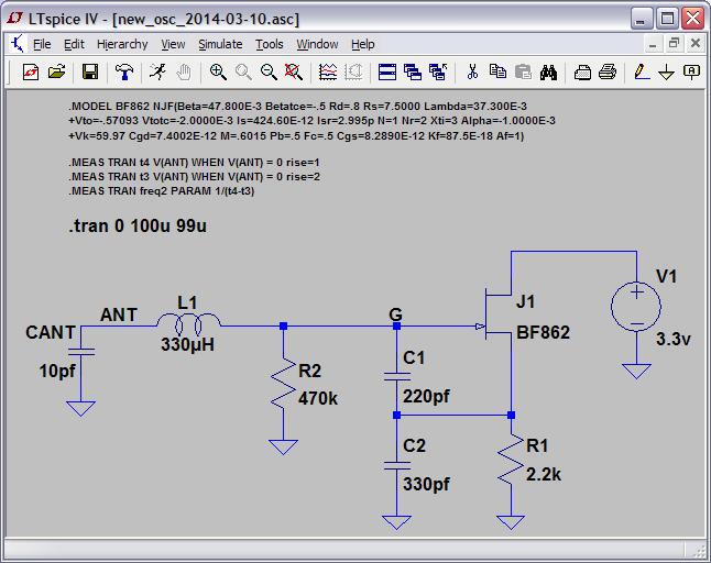
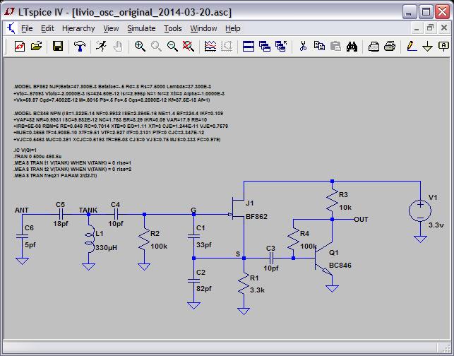
Been playing with oscillators, the Clapp adapted for Theremin use, and livio's Colpitts used in his CapSensor Theremino.  This Clapp is currently running on my bench:

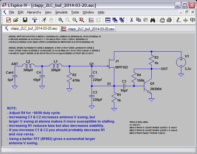
I'm using the split counter-wound tank inductor, and placed some capacitance to ground at the split point (C4).  This obviously cuts into the sensitivity, but it seems to increase stability more than it reduces sensitivity, but I don't have hard numbers to back this up, or any theories.

Some LTSpice waves:

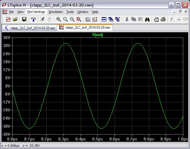
Antenna voltage (for a 5pF antenna) is around 32V peak (64V p-p).

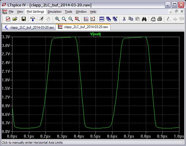
Output of the buffer.  Rise time is around 50ns which should be fine for the FPGA.  Seeing ~100ns in the working circuit, it turns into more or less a sine wave if you grasp the antenna.

Took me over a day of studying, simulating, and benching to settle on using livio's simple but efficient NPN buffer, but with 1/10 the collector resistance.  I wanted to use a FET here but nothing I tried worked as well as a BJT.

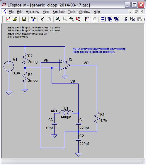
Here is livio's CapSensor Colpitts oscillator for comparison:

After simulating it and changing stuff around I'm not sure why C1 doesn't equal C2.  Also, low bias current (set by R1) is desirable in LFOs to minimize flicker noise and self-heating, but for Theremin use if the bias is set too low there isn't enough energy to overcome tank losses, particularly when a hand touches or grasps the antenna, and particularly when the antenna swing voltage is set rather high, which can produce a stall (which both recover from).  With the tapped split inductor with 10pF to ground and R1=1k I don't see stalling on my oscillator when grasping the antenna (though I do see obvious signs of reduced antenna voltage when it is grasped).

Surprisingly (or not), livio's oscillator can be modified to do very similar voltage swings as those in the adapted Clapp, but not quite as high.  And it can be configured to have very similar sensitivity to the Clapp, but again not quite as high.

If you replace R1 with a FET constant current source and vary the current by changing the set resistor, you can fairly linearly vary frequency.  I don't see this very strongly in simulation, but the bench circuit increases ~1400ppm by lowering R1 to 500 ohms.  This might be a good mechanism to offset any temperature / frequency drift with one or two thermistors.

============

I'm using a new sensitivity metric.  It is (%F change) / (%C change).  To find the maximum or ideal: For a 10pF antenna + 1pF hand, since LC frequency is proportional to the inverse of the square root of the capacitance, we have:

  %F change = [(11^-2) - (10^-2)] / (10^-2) = -0.04654 = -4.654%

  %C change = [11 - 10] / 10 = 0.1 = 10%

  %F / %C = 4.654 / 10 = 0.4654 = %F/%C MTS (Maximum Theoretical Sensitivity)

So sensitivity can (and will here) be stated in terms of MTS, from 0 to 1.

============

0. livio's Colpitts gives 32V p-p at the antenna and 0.28 MTS

1. Removing the 18pF C5 from livio's circuit yields 40V p-p and 0.42 MTS.

2. Further modifying (1) so C1=C2=220pF and R1=1k yields 80V p-p and 0.36 MTS.

============

By contrast, my Clapp as show above has 64V p-p at the antenna and 0.49 MTS.

Reducing C4 to 4.7pF yields 96V p-p and 0.72 MTS.

Eliminating C4 gives 145V p-p and 0.96 MTS.  And increased instability.

Bear in mind that my circuit uses a somewhat inferior FET, if I were to use livio's FET the antenna swing would go up ~25%.  Also note that the above are calculations done from spice data, not actual circuits, and that all inductors were treated as ideal.

I haven't breadboarded livio's Colpitts, for all I know it is more stable than the adapted Clapp.  But I don't really like the look of C4=10pF tank drive & sense, but perhaps that's irrational.

============

I'm coming to the conclusion that I'm a moron for doing any kind of temperature testing with circuits on a bread board.  Need to do an ugly construction or similar oscillator and give that some time in the freezer.

============

[EDIT] Spice here: http://www.mediafire.com/download/8dy1d2iakxakxda/osc_clapp_livio_2014-03-21.zip

Posted: 3/21/2014 12:03:49 AM
FredM

From: Eastleigh, Hampshire, U.K. ................................... Fred Mundell. ................................... Electronics Engineer. (Primarily Analogue) .. CV Synths 1974-1980 .. Theremin developer 2007 to present .. soon to be Developing / Trading as WaveCrafter.com . ...................................

Joined: 12/7/2007

"I'm using a new sensitivity metric.  It is (%F change) / (%C change)" - Dewster

Yeah, I like that! Thats an extremely rational and meaningful metric IMO !

;-)

Fred.

I like the look of your oscillator - and it should be easy to ESD protect it with an antenna discharge tube and a LV transient device from G to Gnd.

Is there any way you can see to adjust the frequency at some LV point in the circuit? I havent had a chance to run the sim on this (or the last) circuit yet [my PC has been tied up running a massive simulation for the last couple of days - hopefully I will get an audio (.wav) file at the end of the procesess so I can hear if my new mixer works as I hope] but as soon as that sim is done, I will play with your oscillator - I just dont want to risk overloading anything and crashing Windows before my present simulation is complete.. Quite funny really, a 60 hour latency ;-).. and thats with a quite fast dual Xeon PC (but horribly slow 15 year old Proteus software - the only simulator I have that produces good quality audio files from schematics - and this will be a big file - several minutes with pitch and harmonic sweeping.. Sadly, I wasnt able to partition the simulation, so it either will complete or it wont, odds are probably 50/50)

Posted: 3/21/2014 2:06:25 PM
dewster

From: Northern NJ, USA

Joined: 2/17/2012

"Is there any way you can see to adjust the frequency at some LV point in the circuit?" - FredM

For small adjustments, reducing R1 from 1k to 500 ohms increases the frequency ~1400ppm on the bench (only seeing 355ppm in spice).  This might be enough to offset any temperature dependencies with one or two varistors.  A varactor from G to ground might give you more range but would probably alter the antenna voltage swing as well.

I added a link to the spice files above.

On a breadboard, on my noisy bench, with my "standard" 250mm antenna, the circuit fires up and is quite stable from the get-go with no real "warming up" drifty period.  Scope trigger delay at 50ms shows <50ns of 60 Hz noise and some very slight drift but that's pretty much it.  From the sensitivity vs. noise and stability I see on the scope I believe this could be played musically out to maybe 0.7 meters.  Drawing ~3mA including regulator and output buffer from a 9V battery (@7.4V, could use a new battery).

Did a quick test at 0.75m with 250mm long x 10mm diameter antenna vs 235mm tall x 115mm wide metal plate: seeing roughly double the sensitivity to my open/closed hand, but also seeing roughly double the 60Hz noise.  If one could filter the 60Hz downstream a plate could be an attractive option over a rod.

Posted: 3/22/2014 3:41:58 AM
FredM

From: Eastleigh, Hampshire, U.K. ................................... Fred Mundell. ................................... Electronics Engineer. (Primarily Analogue) .. CV Synths 1974-1980 .. Theremin developer 2007 to present .. soon to be Developing / Trading as WaveCrafter.com . ...................................

Joined: 12/7/2007

Hi Dewster -

Just been playing with your clapp_2LC_buf_CC_2014-03-21

It really is beautiful! Rock stable, self starting, extremely low harmonics at antenna, low current, and yes - I think the CC Fet has great potential for temperature frequency correction.

For some reason I cannot understand, I cannot get this circuit to run on Proteus - I found before that some oscillator circuits only seem to behave in LT-Spice..

But whatever - Congratulations on this design!  Its really elegant - particularly the way the out-of-phase (voltage WRT Antenna) drive naturally provides exactly the required (minimum) current to sustain oscillation, resulting in a highly stable oscillation of high purity.. I have been messing with non-ideal inductors, changing the resonant frequency and generally abusing your design ;-) and yes - I can get the waveforms to be less perfect etc, but it has stood up to all reasonable abuse I have thrown at it!

Fred.

You must be logged in to post a reply. Please log in or register for a new account.