Let's Design and Build a (mostly) Digital Theremin!

Posted: 3/27/2014 11:40:55 PM
dewster

From: Northern NJ, USA

Joined: 2/17/2012

"Flaws: Antenna voltage does vary a bit with antenna capacitance (marginal) but the real flaw in this design is that frequency will vary HUGELY with any change in shield -> antenna coupling.. Ok if this coupling was COG/NPO, but it most certainly wont be! ;-) "  - FredM

Yes.  This is almost certainly why he dedicates an entire "dummy" channel to compensating for the other active ones.  They tell you to avoid double sided PCB in VFOs because of this very issue.  Could something more rigid, perhaps with some air in there and wider spacing, do a better job?

Posted: 3/28/2014 2:56:16 AM
FredM

From: Eastleigh, Hampshire, U.K. ................................... Fred Mundell. ................................... Electronics Engineer. (Primarily Analogue) .. CV Synths 1974-1980 .. Theremin developer 2007 to present .. soon to be Developing / Trading as WaveCrafter.com . ...................................

Joined: 12/7/2007

"Could something more rigid, perhaps with some air in there and wider spacing, do a better job?" - Dewster

Yes, im sure one could construct an assembly with air (or ideally vaccum) dielectric.. but there is still expansion of the metals, thermal effects on whatever holds the structure together, and of course the thermal effects on any dielectric itself..

For a heterodyning scheme, one might be able to construct an antenna which has a "reference" assembly within it providing the capacitance to a reference oscillator which changes exactly the way the variable oscillators antenna capacitance changes (minus the player ;-) But it would be a lot of work and involve duplicating the VFO circuitry in the REF oscillator exactly..

For rod antennas, I think that perhaps the best might be a construction built using some tube of material like Tufnol which has well defined dielectric properties and is rigid (have the antenna as a metalised deposit on the tubes inner, or as a metalized strip running down the "back" of the inner tube in tight contact with the tube, and have the shield as a semi-circular coating on the outer of the tube) and then have a thermal sensor in the tube which feeds a correction circuit..

For plate antennas I think things could be a lot easier - FR4 has the same charactaristics as some grades of Tufnol - A thermal sensor mounted on one copper face should give accurate enough detection and electronic compensation could be applied.. With a plate antenna it would also be easy to put the whole assembly into thermal insulation, there is no dissipation on the antenna or shield, so good thermal insulation could keep the sensor assembly temperature constant for hours even if there are big changes in the environment .. this may be enough to allow for tuning and the instrument being stable enough.

My view, however, is that with all the other factors (particularly inductor drift if one is using ferrite) having temperature sensing and electronic correction is actually worth the extra circuitry - Oh, its not perfect - but having sensors that can act as positive or negetive correctors summing into an opamp, the output of which corrects an oscillator, is a brute-force inellegant way of solving most problems - Each sensor goes to a 20 turn preset, at centre there is 0 output, and one can adjust each for +ve or -Ve output to taste.. One sensor in the antenna, one or two close to critical components, and you can certainly get "good enough" in most cases...

But I havent tried this new scheme! ;-)

Fred.


Posted: 3/28/2014 5:50:48 AM
FredM

From: Eastleigh, Hampshire, U.K. ................................... Fred Mundell. ................................... Electronics Engineer. (Primarily Analogue) .. CV Synths 1974-1980 .. Theremin developer 2007 to present .. soon to be Developing / Trading as WaveCrafter.com . ...................................

Joined: 12/7/2007

I have moved further discussion on this oscillator coupling scheme to Here


Posted: 4/3/2014 12:16:27 AM
dewster

From: Northern NJ, USA

Joined: 2/17/2012

Today I made a second oscillator with antenna and qualitatively looked at how two oscillators interfere with each other with my scope @ 0.5 ms trigger delay. 

1. Holding the battery powered oscillator in my hand, and "tuning" it by moving my hand near the antenna, I'm seeing a fair amount of disturbance in the bench oscillator out past 1 meter when the frequencies are the same or very nearly the same. 

2. With both oscillators sitting on my bench and sharing a ground, with both antennas oriented vertically and about 0.4m apart, I see a fair bit of disturbance when the frequencies are within about 6% of each other.  This includes significant "pulling" (frequency offset), "tearing" (jitter), and amplitude modulation.

3. Moving the oscillators much closer to about 0.1m apart they have to be about 20% different in frequency to not significantly interfere.

Hmm.  Not quite sure where this is headed.  The interference is somehow both better and worse than I expected.  Better in the sense that two oscillators not too significantly mistuned can operate fairly close to each other.  Worse in the sense that an oscillator fairly far away can pretty much nail another if it's smack dab on frequency.

I also see a significant drop in frequency when simply grounding the battery powered oscillator, which makes sense.

==========

[EDIT] I just increased the scope trigger delay to 50ms.  With the the 0.1m distance and ~20% frequency difference I'm seeing mainly amplitude modulation going on, which is encouraging.

Posted: 4/3/2014 7:02:53 AM
FredM

From: Eastleigh, Hampshire, U.K. ................................... Fred Mundell. ................................... Electronics Engineer. (Primarily Analogue) .. CV Synths 1974-1980 .. Theremin developer 2007 to present .. soon to be Developing / Trading as WaveCrafter.com . ...................................

Joined: 12/7/2007

Dewster,

I am a bit surprised by the effect you are getting from a "distant" oscillator - If the distant one was driving a series LC resulting in a high antenna voltage, and was affecting one with low antenna voltage, I could see it..

Also, 6% is not "close" by any theremin standards - at 100kHz, thats a full 6kHz.. At 250kHz thats well outside the maximum difference one gets on say an EW..

Does this come down to digital requirements proving to be far more critical than the requirements of a heterodyning direct-to-audio theremin? - I suppose that with heterodyning, the net result will be (post mixer) waveform distortion - "jitter" on HF oscillators wont bother the audio much unless extremely severe.

Fred.


Posted: 4/3/2014 1:22:12 PM
dewster

From: Northern NJ, USA

Joined: 2/17/2012

"I am a bit surprised by the effect you are getting from a "distant" oscillator - If the distant one was driving a series LC resulting in a high antenna voltage, and was affecting one with low antenna voltage, I could see it.."  - FredM

Relatively measured just now through a 1pF series cap, the antenna voltages are 4V (bench osc) and 2.6V p-p (hand held osc) with a 8pF / 10Meg probe.  They weren't sharing a ground or a scope or a power supply for the first distance test.  This kind of disturbance bothers me the least because the frequency has to be pretty much spot on to have any effect at all (that I could see on the scope).  I'll have to try it again with a common ground as this would reflect reality better.

"Also, 6% is not "close" by any theremin standards - at 100kHz, thats a full 6kHz.. At 250kHz thats well outside the maximum difference one gets on say an EW.."

It is close by Theremin standards in the sense of pitch and volume oscillator operating points - e.g. for the EWS this difference is almost an octave (260kHz and 450kHz respectively).  I need to experiment more (story of my life) but it seems clear that one can have three oscillators  & antennas on a Theremin as long as they are sufficiently far enough apart in terms of distance / frequency (which is a trade-off; and which seems self-evident in retrospect).  For two volume antennas placed very close together this might require a 25% difference in frequency or more, for the more distant pitch antenna one might also go with something in the 25% range as well since it is controlling something more perceptible to our human senses.

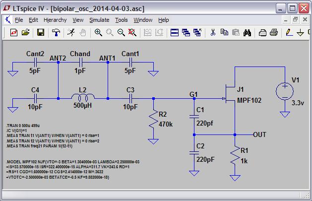
I'm doing these tests in the 1.7MHz range because that's the coils I have handy at the moment.  Ideally I'd like to be running them in the 2-3MHz range like livio suggested in order to avoid strong broadcasts and such, and this almost works mathematically.  Divvying this up geometrically into three (3/2)^(1/2)=1.225 or 22.5% zones gives 2, 2.45, and 3MHz.  These obviously can't be set exactly due to the vagaries of bulk antenna capacitance so some additional slack is likely called for.

And who knows what subtly audible effects might creep into all this, though I intend to heterodyne above 1kHz and average / comb filter to some degree.  I can see why other non-Theremin but essentially Theremin projects with multiple sensors immediately jump on a single stimulus / synchronous detection scheme as it makes a lot of sense from an internal interference perspective.  I need to look at them further I suppose, but they somehow seem inherently AM & RC to me.  And after reading some of Self's "Small Signal Audio Design" (thanks for that pointer Fred!) I rather suspect the use of premium opamps for all of the functionality going on.  If one lowly Radio Shack JFET with a simple hand wound coil can do the same thing, maybe frequency division rather than code division is the better way to go? 

(And it's not like any of these projects are in any real sense actually using multiple code division among the sensors - they talk it up with a bunch of sexy sounding language, but in the end they use a single code to scramble and average out environmental interferers.  If they only use a single code, how immune can they be to conducted crosstalk between hands?  If they were to use multiple orthogonal codes (i.e. Gold codes) they might need some mechanism to make the received power at each antenna roughly the same, something I believe may be impossible with multiple closely spaced receivers.)

Anyway, I have a new respect for the placement of several Theremins in the same room!

Posted: 4/3/2014 8:24:30 PM
FredM

From: Eastleigh, Hampshire, U.K. ................................... Fred Mundell. ................................... Electronics Engineer. (Primarily Analogue) .. CV Synths 1974-1980 .. Theremin developer 2007 to present .. soon to be Developing / Trading as WaveCrafter.com . ...................................

Joined: 12/7/2007

"Anyway, I have a new respect for the placement of several Theremins in the same room!" - Dewster

And this is my problem - because I had 16 operating without problem - and I wasnt doing anything particularly clever! ;-)

These theremins werent directional, all operated at between 400kHz and 500kHz, had about 160V P-P on their antennas (there were a couple that were experimental electronically linearized and that didnt have antenna EQ inductors and only had about 30V P-P)..

Was I just "lucky" somehow? They interacted like hell when their grounds were common, but when the grounds were isolated and they had effectively a 'dipole' antenna assembly with the ground "antenna" below the theremin and the sense "antenna" above it, I was able to detune them enough that they didnt interact - they only interacted if anyone / thing detuned them.

"It is close by Theremin standards in the sense of pitch and volume oscillator operating points - e.g. for the EWS this difference is almost an octave (260kHz and 450kHz respectively).It is close by Theremin standards in the sense of pitch and volume oscillator operating points - e.g. for the EWS this difference is almost an octave (260kHz and 450kHz respectively)."

Yeah - I think my life could have been a lot more difficult if id had volume antennas on my H1 - So its not "fair" to say there were 16 "theremins" - these were only 1/2 theremins.. I may have managed a few more than 8 if they had been full theremins, but suspect I would have been deep in brown sticky stuff if they had wanted 16 full theremins ;-)

Fred.

Posted: 4/4/2014 12:54:29 AM
dewster

From: Northern NJ, USA

Joined: 2/17/2012

Bipolar Oscillator

"They interacted like hell when their grounds were common, but when the grounds were isolated and they had effectively a 'dipole' antenna assembly with the ground "antenna" below the theremin and the sense "antenna" above it, I was able to detune them enough that they didnt interact - they only interacted if anyone / thing detuned them."  - FredM

Along these lines, it hit me today that one might blend the Clapp and Colpitts and make both ends of the wiggling inductor equally sensitive to external capacitance, producing twin bipolar antenna fields:

The voltages at ANT1 and ANT2 are 180 degrees out of phase, swinging about 70V p-p (in Spice).  I have it breadboarded and running, though it won't work without about 15pF of real capacitance hanging off of the inductor (C3 & C4).  Not very sensitive to proximity at the drive point, but the antennas individually seem fairly sensitive.  I was thinking something like this might help cancel out environmental noise / reduce the importance of grounding?  Probably just another dead end.

Spice here: http://www.mediafire.com/download/w5nozden33a58r5/bipolar_osc_2014-04-03.asc

Perhaps my next oscillator will be manic-depressive.  ;-)

Posted: 4/4/2014 2:13:24 AM
FredM

From: Eastleigh, Hampshire, U.K. ................................... Fred Mundell. ................................... Electronics Engineer. (Primarily Analogue) .. CV Synths 1974-1980 .. Theremin developer 2007 to present .. soon to be Developing / Trading as WaveCrafter.com . ...................................

Joined: 12/7/2007

" I was thinking something like this might help cancel out environmental noise / reduce the importance of grounding?  " - Dewster

I think theres a problem..

In conventional theremin topology, one can see the player as a variable capacitance across the tank or antenna resonator, "closing" the circuit.. Even if not galvanically connected to ground, everything conductive (or at least everything not shielded by some other potential) is at least capacitively coupled to ground if not galvanically..

So even if one had a dipole arrangment, these dipoles and the circuit board and the player would all still have coupling to ground...

I never got rid of ground coupling on my H1's - All I did was make this purely capacitive rather than galvanic - The "ground antenna" was quite a large area, and would have coupled to ground substantially - The windings on the power transformer would have coupled to mains ground (N) substantially.

The truth is that I dont fully understand why it worked - I am not alone on this, Lydia's husband (who designed the Tvox) asked me how I was getting the instruments not to react with each other, and  was more than a little puzzled when I showed him...

I originally specified that all the power cables and grounds for the instruments should go to a common power point, and this was what I used when I tested the instruments at home, and they all behaved... I was supplied at the show with a single standard short power extention lead going to the first theremin, another plugged into this for the next theremin, and so on for all 16 - and they just screamed at each other! I suspect it was inductance down the ground line that was the real problem - the instruments at the far end (furthest from the power outlet) were the ones most interacting.. But even so it doesnt make much sense - The PSU design was pedantic and I dont believe HF was escaping down the ground line - I rather suspect that the wire inductance was allowing these "ground" cables to "pick up" radiated RF from one theremins antenna, and there was sufficient HF potential developed to allow signal to be radiated to the other theremin.

But I will never know for sure - All I do know for sure is that no matter what one does, ground is going to be there! - One can either try to fight it, or try to make it work for you. With the H1's I had a large plinth that was ideal for a large area "ground antenna" - this gave good local coupling to the player, and if I ever had a similar job I would do the same again, with or without a galvanic ground connection (I would love the chance to test my H1's with power wiring the way I specified..) But I would be daunted at the idea of having a tuned dipole arrangment.

Fred.

Posted: 4/4/2014 8:07:12 AM
FredM

From: Eastleigh, Hampshire, U.K. ................................... Fred Mundell. ................................... Electronics Engineer. (Primarily Analogue) .. CV Synths 1974-1980 .. Theremin developer 2007 to present .. soon to be Developing / Trading as WaveCrafter.com . ...................................

Joined: 12/7/2007

Just been thinking about ground lead inductance.. Almost started a "Ghosts in the machine" thread to discuss stuff like this - but decided to hijack this thread until it became noticable ;-)

Do we have a situation at times, where inductance in the ground wiring combined with capacitive coupling to ground could actually form a seperate resonant circuit?

And could this perhaps give some explanation for some weird behaviors, and perhaps even occasional "improvements" in range / linearity or whatever - things which are seen but are rarely repeatable?

And could it perhaps be that the choice of lower oscillator frequencies reduces the effect of inductance in ground wires, and that there is a whole can of worms opening as we go towards 1MHz and above with 'conventional' (as in, ground referenced / dependent) topologies ?

Fred.

You must be logged in to post a reply. Please log in or register for a new account.