Let's Design and Build a (mostly) Digital Theremin!

Posted: 4/4/2014 2:00:49 PM
dewster

From: Northern NJ, USA

Joined: 2/17/2012

"Even if not galvanically connected to ground, everything conductive (or at least everything not shielded by some other potential) is at least capacitively coupled to ground if not galvanically."  - FredM

Aye, there's the rub.  I keep thinking there is a balanced way out of this, but with the player effectively grounded it always seems to come back to a ground reference of some sort.

"Do we have a situation at times, where inductance in the ground wiring combined with capacitive coupling to ground could actually form a seperate resonant circuit?

And could this perhaps give some explanation for some weird behaviors, and perhaps even occasional "improvements" in range / linearity or whatever - things which are seen but are rarely repeatable?"

I just did a quick experiment with my battery powered Clapp:

  1.875 MHz - ungrounded

  1.741 MHz - grounded (scope lead)

This is a difference of 134 kHz, or 7%.  An operating point shift this dramatic could easily mess up the fine balance between the tank and EQ leg resonances required by the EWS to linearize pitch response.  Maybe it's that simple?

Posted: 4/5/2014 1:23:43 AM
FredM

From: Eastleigh, Hampshire, U.K. ................................... Fred Mundell. ................................... Electronics Engineer. (Primarily Analogue) .. CV Synths 1974-1980 .. Theremin developer 2007 to present .. soon to be Developing / Trading as WaveCrafter.com . ...................................

Joined: 12/7/2007

Hi Dewster,

Alas, I dont think you can derive any kind of "real" numbers from your above experiment, because by connecting the ground all you are effectively doing is increasing the bulk capacitance "loading" the oscillator - But yes, I fully agree that the deviation is highly likely to move the operating point of the VFO and therefore impact linearity - This is why I have always felt that tuning by adjusting the reference oscillator was wrong - Best linearity IMO can be obtained by having the REF fixed, and adjusting antenna length for tuning (tuning the antenna resonator, not either the VFO or Ref). IMO, changing antenna length is better than adding a tuning capacitor to the antenna resonator, because sensitivity is compensated, wheras a 'wasteful' variable capacitance affects sensitivity.

(I have been playing with an EW board and my screw adjustable antenna, and tuning the null-point with the antenna allows me to use the tuning control to adjust linearity! ;-) - Leaving the "tuning control" (now used as a linearity control) in a set position and tuning using the antenna will, I believe, give consistant linearity regardless of normal changes in capacitive environment - but I wont say this until I have confirmed it ;-)

 I have sketched how I see the configurations:

Normal GROUNDED OPERATION:

Player is coupled to ground capacitively (C6 - ideally 100pF or more). L1 (the ground wire) is low Z, ( low R, Low L) and C1 is effectively shorted. C5 is small (direct capacitive coupling of player to circuit boards 0V, which probably only becomes noticable when the player is close to the theremin), C3 is small (direct capacitive coupling between antenna and circuit boards 0V)..

Main capacitive path is from antenna to ground via player (C4<->C6) and to ground via background (C2) giving a total capacitance of    (C4<->C6) || C2

UNGROUNDED OPERATION:

Theremins 0V is only coupled to ground via C1 and C5 which are both small - Antenna couples to ground via C2, but as ground is only coupled to the circuits return path (back to 0V) through C1 and C5, the antenna sees a much smaller capacitance. The same is true for the player, whose coupling to ground must go in series through C1, and is therefore greatly reduced.

INDUCTIVELY GROUNDED:

IF this is significant inductance in the ground lead (long cable to ground for example) it will behave in the frequency dependant way inductors do - higher impedence as the frequency increases.. If / When this happens, C1 will no longer be "shorted" and the possibility of C1 || L1 forming an important resonant entity perhaps becomes real.

---------------------------------------------------------

I wrote the following before I wrote the above - I think the above is more simply explained.. the following repeats the above less clearly I think..

----------------------------------------------------------

With an ungrounded theremin, "0V" coupling (the boards "ground") to the player is mainly determined by C1 and C5 which are  small capacitances - assuming C6 is comparatively so large (~100pF) as one could regard it as a "short". C2's effect will be greatly reduced because it is effectively in series with C1. IF player coupling to ground is poor, C6 becomes significant (as in, too small) and needs to be taken into account, both when the theremin is grounded or ungrounded

If (as with my H1 setup) one cannot connect to ground, then one needs to increase C5 (and also probably C1) by increasing the 'plate' area at the junction of C1+C5 (the 0V connection to the board)

C1 is the critical component - with a grounded theremin, this is "bypassed" by the galvanic ground connection (shown as L1) IF L1 is low and resistance is low - As soon as C1's "blocking" function is removed, C2 is no longer in series with C1 and its effect is greatly increased, as is the effect of the player, as their 0V coupling is no longer "blocked" by C1.

But now we get to L1 - IF this is significant (long cable to ground for example) it will behave in the frequency dependant way inductors do - higher impedence as the frequency increases.. If / When this happens, C1 will no longer be "shorted" and the possibility of C1 || L1 forming an important resonant entity perhaps becomes real.

Fred.

ps - C3 is shown for completeness, its coupling from the antenna to the board.. Also, these capacitors and inductors are not "physical" components - they are an equivalent circuit showing "components" "formed" by the environment.

Posted: 4/5/2014 11:46:26 AM
dewster

From: Northern NJ, USA

Joined: 2/17/2012

Hi Fred,

Regarding the EW, I agree entirely, and it is interesting that with your variable length antenna the pitch knob will likely become more of a linearity adjustment.  I still think it is perhaps easiest and best to just forgo linearization of the near field, particularly with the difficulty in tuning, and the recently discussed complex EW Pro resonant modes giving trouble at start up.  Make the Theremin pitch field wide enough so people don't need to spend significant time there during normal play.  I think audiences like to see more distance between hand and antenna as well, as it looks more impressive.

I wasn't thinking about the stray capacitances C3 and C5, very nice that you have included them and summarized the configurations.  Your text and figures would make a nice addition to a book or paper on the subject!

The oscillator needs some kind of foothold to wave the antenna voltage around, and I keep thinking there must be a way to somehow make this symmetrical rather than ground referenced.  A second identical antenna waving out of phase doesn't seem to be the answer as it would cut sensitivity in half and be susceptible to disturbance and noise.  Ah well.

==========

I'm kind of stuck studying VFO circuits and trying to figure out how best to buffer the output of the crazy JFET to my logic.  A single NPN (ala livio's circuit) works, but any time you use a BJT or JFET with serious gain you run into Miller capacitance, which would then couple the output into my resonating capacitances with temperature dependence.  I could use a JFET or BJT as a voltage follower, and then run this to a gain transistor, but that seems like it's getting overly complicated and draws significant current so there is more ohmic heating going on.  What to do.

==========

[EDIT] Was starting to get insecure about my latest JFET oscillator so I thought I'd do another comparison to livio's Colpitts both in Spice and on the bench.

I see now why he uses a larger lower capacitance in the divider - this tends to boost the output voltage swing without increasing transistor bias current, though it also makes it stall easier.  The tiny capacitor driving the tank reduces sensitivity ratiometrically with the antenna capacitance, but going below about 10pF keeps it from starting on my breadboard so you're limited to roughly 1/2 the sensitivity right off the bat.

My Clapp with the split tank inductor and 10pF to ground is a compromise in sensitivity giving >2/3 of the theoretical max, but it doesn't stall and can work down to quite low average drive currents (<1mA) while providing around the same voltage swings as livio's Colpitts.  The same trick of increasing the lower capacitor similarly increases output swing, but at the expense of more amplitude reduction when touching the antenna.  The Clapp doesn't work so hot without the split & tapped inductor, if I hadn't stumbled across that I'd probably be considering the Colpitts instead.

I've read that the Colpitts tends to keep the tank voltage constant, Clapp tends to keep the output voltage constant.  I can't say I see much difference between the two in this respect when they are adapted for high voltage Theremin use.  I've also read that bias currents should be kept minimal to reduce noise, but I can't say I've seen any direct evidence of this either.

Posted: 4/8/2014 5:01:27 PM
dewster

From: Northern NJ, USA

Joined: 2/17/2012

Been spending way too long looking at oscillator buffering.  With a 3.3V supply there isn't much opportunity for gain.  But gain isn't really necessary, while isolation is.  A FET follower is the simplest and gives the best isolation so I've been concentrating on that. 

The above is what I may settle on.  It draws 2.4mA on the bench (with regulator) and gives a somewhat sine-like 2.5V p-p output that doesn't jump towards + or ground when the signal is attenuated by touching the antenna, and will drive significant capacitance.  It's only going to drive an FPGA pin a short distance away, but I don't want digital noise creeping back into the sensitive oscillator.

Spent some more time this morning with livio's oscillator investigating 60Hz interference.  The inherent bandpass nature of the Colpitts (grounded tank inductor) had me worried that it might be better at rejecting 60Hz than the Clapp above.  Luckily (?) I have an extremely noisy LED lamp on my desk that emits 60Hz like crazy via the AC adapter.  I measured ~20ns of 60Hz FM with livio's oscillator, ~50ns with the Clapp above.  Considering livio's Colpitts has ~1/3 max sensitivity and my Clapp has ~2/3, it's pretty much a wash in the 60Hz department.  So I believe I can stop worrying about this issue for now and deal with it later as necessary.

It can sometimes take a person months to find a bit of wheat amongst all the chaff in this field!

Posted: 4/28/2014 2:47:36 AM
FredM

From: Eastleigh, Hampshire, U.K. ................................... Fred Mundell. ................................... Electronics Engineer. (Primarily Analogue) .. CV Synths 1974-1980 .. Theremin developer 2007 to present .. soon to be Developing / Trading as WaveCrafter.com . ...................................

Joined: 12/7/2007

Hi Dewster -

I have been obsessing over how one determines the difference frequency accurately for a digital heterodyning system without having to go via an analogue integrator and comparator.. The inaccuracy of my D-Latch scheme really pissed me off!

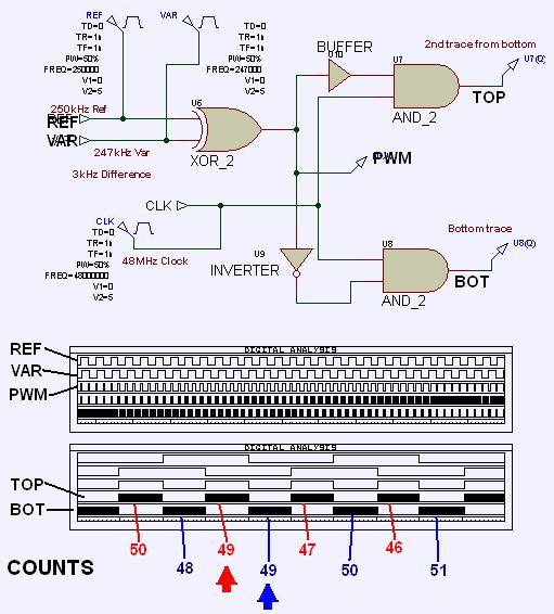
Been playing with all sorts of complex logic schemes which I think could be implemented in a FPGA or PSoC quite easily - but the basic idea boiled down to this.. Rather than just using the Reference and Variable oscillators, the logic also takes the counter clock - by using these 2 oscillator and a (much) higher frequency clock I believe it may be possible to derive the frequency to the accuracy of one (HF) clock cycle.

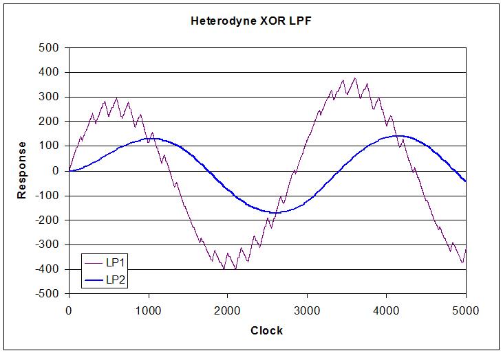
If we take the output of an XOR that's driven from the oscillators, the pulse width from this output will be exactly 50:50 twice during every (difference frequency) cycle - this corresponds to the zero crossing point of the integrated PWM (triangle) -

If we use the (counter) clock (or a faster clock) to count the low time and high time output from the XOR, then when these times are equal, we have determined the zero crossing point.

And one has eliminated the need for any analogue, but still have the advantages of heterodyning.

Fred.

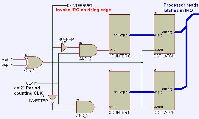
(my simulated logic involved an up/down counter, resetting this counter on the rising edge from the XOR (after having captured the value of the counter), incrementing the counter with the count clock when the XOR output was high, decrementing the counter when the XOR output was low, and using the captured counts to determine zero crossing.  I used a 200MHz clock to count the XOR output so as to capture high difference frequencies - one can calculate required count rate and bounds (as in, whether to accept say a span of -1 to +1 as a "0") to ensure that one captures the zero crossing for whatever maximum difference frequency one needs to work with)

I played with a PSoC 5 implementation of the above, where I didnt use an up-down counter but used a pair of "timer" UMs, one to count the EXOR low time, one to count the high time - these counters were not reset, but the counts were captured on rising and falling edges from the XOR, and an interrupt was generated on each capture event - the interrupt handlers taking care of determining the zero crossing.. This is a safer way of dealing with things because one does not need to hit an exactly equal M/S from the XOR - one can determine if one has gone through a zero crossing event by comparing the previous interrupts data to the current one. Doing this one does not need as fast a clock (The PSoC UM's operate at maximum 48MHz) but can be sure of detecting every zero crossing.

Once a zero crossing is detected, one can disable the timer UM interrupts for say 20us to prevent any spurious triggering and to give the processor time for other tasks / pending interrupts. (2 interrupts coming in every 4us for oscillators running at ~250kHz isnt too difficult to deal with by the PSoC 5 processor, but if the oscillators were to go up to 1MHz and a slower processor was used, it could get tight - I am sort of toying with using a PSoC 1 and this scheme for implementing CV output ;-)

ADDED ->

Writing things often makes them clearer to myself.. Following writing the above I realised the process could be greatly simplified.

One does not need to look for "Zero Crossing" - If one is only looking at one edge of the triangle, this can be performed with one counter, and one can look at this counters value while it is going in one direction (incrementing or decrementing) and compare the count to some constant to determine a crossing point.

Even if looking at both slopes one can use a single counter - Probably the simplest (fastest IRQ handler) would be as follows:

When PWM is (say) high, hold the clock counter in reset.

when PWM is low, the counter counts the high speed clock.

On the rising edge of the PWM,  capture the count value and generate an interrupt..

One each interrupt check whether acquired count is incrementing or decrementing (Check whether the previous captured  count was greater or less than the present captured count, after calculating any roll-over if the counter is not reset after each capture*) and flag a 1/2 cycle when "direction" changes (as in, if captured counts had been increasing but change to decreasing), or a cycle when direction changes one way (change from say increasing count to decreasing one).

The interrupt handler only needs to look at the count values and determine whether these are increasing or decreasing - a change in direction would be correspond to the peaks of the triangle wave.* Not a good scheme - see update

*(one does not actually need to reset the counter - could use the PWM to gate the count clock, and process the count / roll-over in the IRQ handler)

UPDATE -->

Having now run a load more simulations, the peak detection scheme is probably not the best - PWM pulses get extremely narrow at the peaks (actually, they vanish altogether at the +Ve and -Ve peak), and it becomes difficult to capture the exact point of transition.

The best schemes seem to be crossover detection somewhere near the mid count - the best is probably comparing the mark to the space, as one is increasing while the other decreasing and VV, giving a sharper detection of crossover.

A constant against which the count is compared also works well, particularly if placed near the mid-count - its simpler to implement, but results in unequal spacing of the output pulses.. so one needs to only use output from either the rising or the falling counts - this method is identical to using an analogue comparator looking at a triangle waveform and comparing it to a fixed voltage - you can only use either the rising or the falling edges from this comparator unless you can maintain the reference at exactly the mid point.

If at all possible, my choice would be to compare mark to space - As I see it, if a clock >= 2* the frequency of the period clock is used for the "PWM MS Counter" then one should get the same or better timing accuracy as one gets from analogue integration and analog comparator - But, in fact, I believe the resolution will be better - one does not have any analogue noise or HF leakage into or out of the analogue comparator, there is no frequency dependent or temperature dependent analogue stuff to worry about at the integrator / filter (you dont need a filter or any analogue stuff to do the heterodyning).

The "PWM MS Counter" can be small - 8 bits is probably more than enough for most situations.. With oscillator frequencies at ~250kHz, the longest PWM period will be 4us, so would only overflow an 8 bit counter unrecoverably if the clock exceeded 63MHz.

Posted: 4/28/2014 3:39:04 PM
dewster

From: Northern NJ, USA

Joined: 2/17/2012

Hi Fred,

After reading the description of your approach above, and perusing my Excel sim of digital heterodyning, my feeling is that any scheme which even indirectly employs the timing of the resulting XOR edges is unfortunately doomed to boil down to the DFF case (or worse).  And pegging events to these edges seems to introduce low frequency aliasing that is much more difficult to remove than the original HF aliasing.

I think we're stuck with heterodyning followed by 2nd or perhaps 3rd order filtering (a cascade of two simple first order sections seems to be sufficient in simulation).  Any of this can be in the digital or analog domain.  The Open.Theremin is quite clever by offloading these calculations to the analog domain.  To do this digitally, the filtering has to happen on each high speed clock, which requires dedicated high speed hardware.

[EDIT] I guess I don't see how an up/down counter (first order filter) gets around the multiple zero crossing scenario seen here at times ~2800 and ~4300:

Or am I missing something?  You could pick the first crossing I suppose, but there would be systematic error.  Even the non-multiple crossings are linear estimates and not as precise as they could be, whereas the second order filter output is a much better estimate, and monotonic to boot.  (I believe there are parallels between filter order and polynomial fit order.)

Posted: 4/28/2014 5:09:03 PM
FredM

From: Eastleigh, Hampshire, U.K. ................................... Fred Mundell. ................................... Electronics Engineer. (Primarily Analogue) .. CV Synths 1974-1980 .. Theremin developer 2007 to present .. soon to be Developing / Trading as WaveCrafter.com . ...................................

Joined: 12/7/2007

Hi Dewster..

I aint giving up! ;-)

" I guess I don't see how an up/down counter (first order filter) gets around the multiple zero crossing scenario seen here at times ~2800 and ~4300:" - Dewster

Is the counter a first order filter in this context? - I suppose it could be seen as such..

As I see it, with any digital scheme, one is having to deal with quantizing - The counter used to determine the period will introduce error - regardless of how the period is "generated", whether this be through analogue or digital comparison.

As I see it, as long as the transition from one state to the other (the comparator output) is as, or more precise than the error caused by the period clock, there will be no increase in DFF

If you see the PWM output from as a linearly increasing mark with a linearly decreasing space (and the reverse on the down slope), then if one has  counters numerically tracking the MS there are no " multiple zero crossing scenario" - these scenarios are only the result of the charge / discharge function - if (as with an up counter) one was able to put a diode in the integrator, one would not get any discharge, so would get no zero crossing problems, but with analogue you would have the problem of the integrator going to rail and staying there... With a counter, you can let it roll-over, and compute the actual counts from previously captured count.

I do see that a simple system like I am postulating could probably be improved - One could, for example, "fine tune" by computing exactly where the cross-over occurs from counts read before and after the crossover has been detected.

Here is a simple diagram of hardware - I plan to shove this into a PSoC and run it from my sig-gens ASAP.. Some things just need to be tested.. ;-)

Oh - that should be ">= 2* Frequency of period counting clock" not period ..

If this clock is really fast, bigger counters would be needed, but one could get (I think) precise location of the crossing point which could be used to fine-tune the period count... It could actually perhaps be used to increase the effective number of bits in the resolution of the period count.

Posted: 4/28/2014 8:31:56 PM
dewster

From: Northern NJ, USA

Joined: 2/17/2012

Hi Fred,

I guess I'm thinking about this in the frequency domain, and that's where the futility of "mechanically" determining the crossover precisely in the time domain is most obvious IMO.  We're given a low frequency signal mixed in with a high frequency signal, the relative phase of which moves around due to the variability of the heterodyning process.  (The unwanted harmonic content is actually somewhat worse than this if we use a digital XOR to heterodyne.)  We're trying to determine the exact frequency (within the limits of our measuring clock) of the low frequency signal.  If we sufficiently filter (2nd order or better) then the HF content is pretty much gone and measuring is easy: just look for the crossover point.  If we don't sufficiently filter (integrator, 1st order LPF, up/down counter, "dueling" modulo up counters, etc.) then the HF content will confound our time domain measurements, possibly leading to errors larger than our measurement clock, and possibly cyclic long-term (low frequency) error periods.

And, I could be wrong, but given two modulo up counters instead of one up/down counter, there remains an issue with multiple crossover ambiguity.  You have to compare the counts (subtract one count from the other or similar) to know what's going on, which makes it equivalent to the up/down counter (or up/down integrator) scenario.

If you sufficiently filter, you can look at the filter accumulator to get sub-clock interval error information.  (This is kind of like DDS where the accumulator can be thought of as running in continuous time, but you can only "see" the information in it on the clock.)

Posted: 4/28/2014 9:34:17 PM
FredM

From: Eastleigh, Hampshire, U.K. ................................... Fred Mundell. ................................... Electronics Engineer. (Primarily Analogue) .. CV Synths 1974-1980 .. Theremin developer 2007 to present .. soon to be Developing / Trading as WaveCrafter.com . ...................................

Joined: 12/7/2007

Hi Dewster,

Not saying your wrong - my level of digital comprehension is constrained mainly to schematics I can draw and visualize, so I haven't got any real "feel" for what you are saying..

I dont really see this as extracting a LF signal from a mix of LF/HF, I see it as determining the instant at which a triangle crosses its mid value - I know that WE are extracting the beat by doing this, but AFAIK the circuit doesnt know this! ;-)

Here are some simulations I ran using a 48MHz clock and the gating shown in my last -

The bottom plot is an expansion of the zero-crossing area and shows the mark and space counts going in opposite directions but crossing at the mid point.

The counters are unidirectional - their actual count value is unimportant, all thats important is the number of counts clocked in each PWM cycle (about 2us for the given input frequencies) and their 'distribution' in the mark and space time slots.

With the above clocks, precision is poor - but it seems able to detect the mid point on both the triangle rising and falling edges - there is never any crossover error.(as in, the mark counts increase or at worst stay the same on the way up, and if they stay the same the space count decreases anyway so the total count in each period only has a 1 count error that I have seen - I haven't seen any spurious change in count 'direction' - not saying this is impossible in real life though ;-) I am reasonably sure that with a 200MHz clock in say an FPGA, and perhaps a bit of simple 'corrective' software in the interrupt handler (to correct the period count [by this I mean the counter which uses this X-Over detection] value by perhaps a bit or two)  one could get rid of analogue filtering.

(Should just add that there were some messy counts at the top and bottom peaks, where the PWM gets real narrow - but this is easily corrected in the IRQ handler - simply throw away counts which are too small or too large and therefore cannot be close to the mid cross-over.. Using a single IRQ to deal with both mark and space counts makes this easy.. This same IRQ handler would also probably read the separate period counter when an X-Over is detected, and I hope be able to get as accurate a period as is possible by using data from all the counters and their prior counts at this instant)

But Ive been wrong before ;-) ... I'm actually much more interested in this idea for an entirely non-theremin related job - I don't really give two hoots whether digital theremins have filters or not! ;-)

Fred

Hmmm.. I can see some potential problems when the difference frequency is low - I think about 2kHz difference is as low as one can go with this scheme and the clocks picked, otherwise there can be PWM cycles where counts dont change or worse could change based on noise. Not a problem for my intended application, and probably not too much of a bother for digital theremin application where one is likely to 'bias' the operating frequency anyway - but a real bother for my other possible application as a detector to determine period on conventional theremins.

Also, Var and Ref must have precise 50:50 duty cycle, so a FF is required for each - this will reduce the input difference by 50% - with oscillators running at say 200kHz (divided to 100kHz) and 200MHz count clock, one would probably need something like a 5kHz "offset" to get good enough detection of the crossing.

- And I may be absolutely out of my depth here anyway - I have a real problem getting my head into frequency domain when it comes to digital stuff like this....

I should probably have posted this on the crazy ideas thread..

Posted: 4/29/2014 7:37:55 AM
dewster

From: Northern NJ, USA

Joined: 2/17/2012

Fred, your simulation brings up some deeply interesting points.

As you note, the precise 50:50 duty cycle is very important.  The reason my Excel sim has spurs around zero crossing is due to the use of DDS, which introduces +/- 1/2 system clock jitter.

Anyway - not an attack, just an observation - given your data above:

50, 49, 47, 46 ...

   48, 49, 50, 51 ...

one would be hard pressed to say on exactly which high speed system clock the zero crossing happens.  Narrowing it down to even 50 or so clocks would be a challenge.  With more data one could doubtless average / filter and come up with a better / closer estimate.

I was (naively) thinking that filtering to the point of monotonicity was sufficient, but it seems clear that further filtering is likely necessary to resolve down to system clock levels.  Filtering that perhaps isn't trivial due to non-base band or offset heterodyning in a digital Theremin (harmonics closer to the fundamental).  I was kind of wondering why the Open.Theremin uses third order here, this is likely the answer.

Not thinking 100% straight (lack of sleep) so I'm having trouble producing a simple example, but I suspect it is possible to have a fundamental frequency emerge from heterodyning that has zero crossings which don't directly align with the edges of either square wave input?

You must be logged in to post a reply. Please log in or register for a new account.