Let's Design and Build a (mostly) Digital Theremin!

Posted: 4/29/2014 9:17:56 AM
FredM

From: Eastleigh, Hampshire, U.K. ................................... Fred Mundell. ................................... Electronics Engineer. (Primarily Analogue) .. CV Synths 1974-1980 .. Theremin developer 2007 to present .. soon to be Developing / Trading as WaveCrafter.com . ...................................

Joined: 12/7/2007

" I suspect it is possible to have a fundamental frequency emerge from heterodyning that has zero crossings which don't directly align with the edges of either square wave input?" - Dewster

Im not sure about this - but more to the point not sure it would matter.. once the signals are mixed in the XOR, isnt the only thing of importance (in terms of cross-over) the M:S ? And if the zero crossing (50:50 MS) didnt align with the input clock/s, would this matter? - As I see it, one could set the "crossing" threshold wherever on wanted (compare the PW against some constant) - comparing M to S just seemed like a way to get higher resolution.

Please dont worry "not an attack" - I need to bounce ideas like this as a form of sanity checking! ;-) - And yes, determining the X-Over with any precision is going to be difficult - Higher frequency clocks, lower frequency oscillators (or pre-division of these oscillators) and large offset difference frequency will be required if I want to get much improvement on a simple D-Latch.. For most (perhaps all) applications, this idea probably isnt worth the design effort let alone implementation... I never realized this when I posted the idea, but I do now  - largely because I set out to prove that I was right by doing comprehensive simulations, and these showed that I wasnt as "right" as I thought I had been! ;-)

But as with all ideas, unless shared, one cannot get feedback - and ideas (and the feedback) can get others thinking about things differently and perhaps finding solutions or generate new ideas.. And if (and sadly, this is where it falls down) others then expose their ideas (rather than skulk off and secretly exploit others freely given work) then things advance.

Fred.

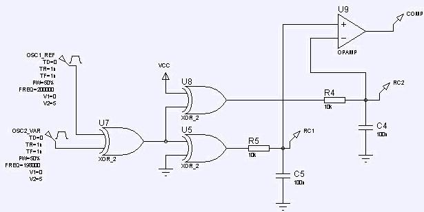
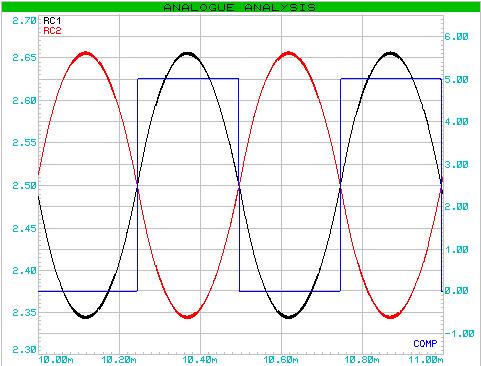
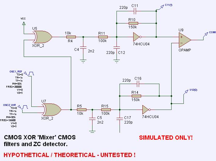
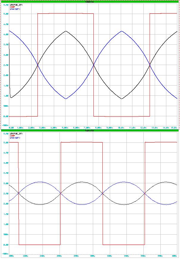
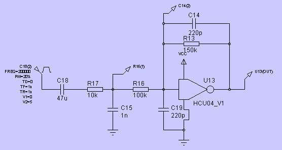
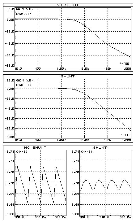
Oh, BTW - I do agree that with analogue integration of an XOR PWM, one does need as high order filter as you can manage - the better the filter, the more accurate the detection seems to be - For the job I am looking at using this design on, I have been using a 4 stage CMOS buffered LPF.. This design is absurdly cost critical and space constrained, which is one reason I am looking at eliminating the analogue integrator and comparator, and hoping to use a small low cost PSoC 4 ($1) - But I will be also be looking at using the PSoC filters and comparator UM's - this will probably do the job better - and I can have XOR, filter and comparator in the chip so still (hopefully) achieve what I need.. perhaps with one external RC.

-> LOL ;-) I cant just let this go.. Now gone back to ,my D-Latch scheme - I think that using the clocking ideas above I can actually count the error component using the period clock and capture this, which would allow this valur to be simply added or subtracted from the period count.. stay tuned - another probably silly idea is likely to come soon ;-)

Posted: 4/30/2014 3:47:46 PM
FredM

From: Eastleigh, Hampshire, U.K. ................................... Fred Mundell. ................................... Electronics Engineer. (Primarily Analogue) .. CV Synths 1974-1980 .. Theremin developer 2007 to present .. soon to be Developing / Trading as WaveCrafter.com . ...................................

Joined: 12/7/2007

Well, I cant find an all digital way to accurately locate the X-Over.. Im sure there must be a way (without complex digital filters or the like) but am probably wrong..

In examining the idea of digital comparison of the M/S from the PWM, I reverted back to an analogue version of this idea just to compare it (see if it worked as I expected the digital to work)

Not sure if anything is gained - but this analogue version using two simple integrators seems to work quite well - Ok, the tc of these integrators is large in this simulation, so one gets a smaller amplitude to compare (and consequential possible noise issues) - but there is an advantage of comparing two waveforms going in opposite directions, guaranteeing (?) exact center crossing - perhaps with 2nd order integrators on each input one could get a marked improvement (?) 

(I am sort of wondering whether this differential comparison would work better than comparing a fixed reference to a single waveform - whether having 2 2nd order filters with differential comparison would beat a 4th order filter on a single waveform compared against a fixed reference... I feel that it will - but have no idea about how to test this hypothesis)

ps - U8 is acting as an inverter and U5 as a buffer - simply used these to keep delays the same.. in practice only an inverter for U8 is likely to be needed.

This give clean crossing at >=2kHz difference, A single extra X-over glitch @ 1kHz and a mess below that.


Posted: 4/30/2014 10:04:52 PM
FredM

From: Eastleigh, Hampshire, U.K. ................................... Fred Mundell. ................................... Electronics Engineer. (Primarily Analogue) .. CV Synths 1974-1980 .. Theremin developer 2007 to present .. soon to be Developing / Trading as WaveCrafter.com . ...................................

Joined: 12/7/2007

ok - I think this is my last on this...

Simulation of a differential comparison using better filters - this one works cleanly over the whole audio spectrum, but shown for waveforms (difference) frequencies of 100Hz and 10kHz. Amplitudes are big enough to give adequate SNR.

Posted: 5/1/2014 3:15:19 AM
dewster

From: Northern NJ, USA

Joined: 2/17/2012

Fred, I'm looking and thinking, give me a bit (family visiting this weekend, volunteer projects, nervous breakdowns, etc. taking 101% of my time).  I believe generally when one can measure a single waveform compared to ground (if it has a long-term AC ground reference - like a simple RC does - leaky integrator) then SNR may be better if that single waveform is compared to ground rather than two separately derived waveforms to each other.  But that's only SNR, and just something a communications prof. demonstrated to me at one point when I approached him with a synchronous receiver-type circuit I was working on (I asked him if I should be integrating over the dark period of a sensor that was illuminated by an IR LED with 10% active duty cycle and compare it to the active integration period - he said no due to the added noise - different enough to likely not be applicable here - wish I had a comm prof at my beck and call now!).

Also, C12 and C17 confuse me a bit: are they there because the (-) input isn't a very ideal virtual ground (low gain)?  For an ideal opamp this would be something like bootstrapping (I think?) which might make the caps moot in terms of response?

Posted: 5/1/2014 12:58:06 PM
FredM

From: Eastleigh, Hampshire, U.K. ................................... Fred Mundell. ................................... Electronics Engineer. (Primarily Analogue) .. CV Synths 1974-1980 .. Theremin developer 2007 to present .. soon to be Developing / Trading as WaveCrafter.com . ...................................

Joined: 12/7/2007

"Also, C12 and C17 confuse me a bit:" - Dewster

Those capacitors shunt  AC / HF to low z ground (by ground I am talking about the -V supply not the mid supply at which CMOS centers)  .. And you are right - with an op-amp they wouldn't do much  (or anything).. I found (in actual physical circuits) that the response wasn't as good as I expected, and on examining, discovered quite a lot of signal on the inverter input.. Plonking a C there was the simplest fix (a better fix is using 3 inverters to increase gain, with the output inverter being 4 inverters in parallel to improve drive - this is a good solution if one needs higher output drive anyway - but if one doesn't, a simple shunting C on the input improves the filter)

I found that the optimum value for this C was the same value as the integrator capacitor - larger values also work though... I cannot explain why copying the integrator C value works - perhaps its because the Zs are equal.

When it comes to filters (particularly ones made with low cost far-from-ideal components) I get well out of depth with regard to designing good ones - So its often more about playing with a breadboard and simulations than actually "designing" - For conventional op-amp based filters I have design tools that give accurate results, and often use these to get the 'core' design - but porting these designs to CMOS they often don't work anything like the op-amp realization.. And sometimes the simulations behave quite far from a physical circuit (but are usually usable) so physical testing of CMOS linear circuits is absolutely essential.

Fred.

Below are some SIMULATIONS - These don't accurately reflect real circuit operation (the attenuation provided by the shunting C seems better in reality) but gives an idea of the signal seen on the inverter input and the frequency response with / without the shunting capacitor. Increasing the value of the shunting C gives marked reduction of signal seen on the input in simulation, but this doesn't appear to be to be reflected well in reality.

Top 2 traces are frequency response, bottom 2 traces show signals on the inverter input.

Shown is with a 200kHz 20% MS square wave input (PWM for two ~100kHz oscillators would be ~400kHz). "Shunt" is C19

ps - note that the dbs of the frequency responses below are scaled differently - @1MHz the upper trace drops  below -60db, the lower trace drops below -80db... There is a substantial difference between the two responses, but the scaling obscures this a bit. I am not sure how "true" these comparisons are, but in practice fitting C19 does certainly improve performance. I have NOT however played with these filters in combination with comparator as presented above.

ps - im just dumping stuff here..  Deal with family matters ;-) this is all unimportant! Hope all goes well! ;-)

Posted: 5/1/2014 7:17:55 PM
dewster

From: Northern NJ, USA

Joined: 2/17/2012

Nice Fred!  I think I've experienced the non-ideal linear biased CMOS inverter summing point on the bench.

Whenever I see an RCR input to an op-amp (-) input, say in an XOR PLL loop filter, R17 and R16 are the same value - so the parallel combination of them is the impedance seen by C15.  Doing this might allow you to reduce C18 and C15 somewhat, but maybe I'm missing something?  Maybe you are using a low impedance RC (R17, C15) followed by a high impedance RC (R16, C19) to reduce loading and make it more like an idea second order network?

==========

[EDIT] (Warning: dreaming ahead) The more I contemplate the transmissive approach to Theremin technology the more it seems like the answer to everything.  One transmitter (the player), one frequency (or code or whatever), as many receivers as you want with little to no interaction.  Traditional Theremins work better when everything is properly grounded, or at least with a decent return path to the player, so why not use the return path explicitly as excitation?  You could use possibly use sine waves as excitation, because tuning it might be fairly simple if interference is encountered.  The excitation wouldn't even have to be a steady frequency because the reception would be synchronous to whatever it's doing.  But people probably wouldn't want to be required to attach a wire to themselves (even a magnetic ring for the Hall Effect approach may be bordering on onerous), there could be a shock hazard if transmission isn't via a large capacitive plate under your ass, etc.

Posted: 5/1/2014 8:13:31 PM
FredM

From: Eastleigh, Hampshire, U.K. ................................... Fred Mundell. ................................... Electronics Engineer. (Primarily Analogue) .. CV Synths 1974-1980 .. Theremin developer 2007 to present .. soon to be Developing / Trading as WaveCrafter.com . ...................................

Joined: 12/7/2007

Hi Dewster,

You probably aren't missing anything - I cannot give a "design" rationale for what I did - I started out with a conventional op-amp filter to clean up the audio signal from a CMOS analogue mixer - this was/is a wave-shaping mixer, and I wanted the audio harmonics to to be unattenuated to at least 15kHz, but steep cutoff for everything above 20kHz.. Ended up with a 4th order filter to do the job..

I then started looking for a simpler / cheaper circuit using linear CMOS (to complement the CMOS mixer - as in, low voltage operation, no requirement for a mid-voltage etc) and ended up getting a good enough filter using  spare inverters.

The integrator / filter shown above is one section of this "design" with a lower frequency roll-off.. the original "design" was done largely through trial - substituting components in the simulation and on the plug-in breadboard.. There is nothing 'precision' about this 'design' !  ;-)

Having a small R (R17) with large C (C15) tuned to about an octave above the required roll-off, and following this with an 'active' integrator having R(R16) 10* larger than the first integrators R (R17) and setting this active integrator to roll-off at the required frequency, and then placing a 'copy' of this integrators C (C13 = C19) on the inverters input to ground seems to work for whatever frequency I want - and if I change any relationship, it doesn't seem to work so well....

But I don't know why!*  (I have noticed that the loading on the output of unbuffered CMOS is critical - changing the feedback components dramatically affects the response, as does loading the output into following stages)

I would feel a lot happier knowing why! - One reason why perhaps I am likely to use op-amps unless I absolutely must use CMOS.. But as far as I can see (and hear) my mixer based on a 4007, two JFETS (to provide DC wave-shape control) and an unbuffered hex inverter (which is part of the mixer and doubles as the filter) is as good as what I can get if I substitute some inverters for op-amps.. But its early days - the mixer is undergoing refinements (the JFETS are awkward - I dont want HF on potentiometers, so am looking at using digital pots - dont want to use OTA's because they dont behave well at low supply voltage, and H11F1's are expensive).

Fred.

" Maybe you are using a low impedance RC (R17, C15) followed by a high impedance RC (R16, C19) to reduce loading and make it more like an idea second order network?"

Yes - I think that is whats happening! - I didnt intentionally do this.. I simply stuck a filter on the output from the original first-order integrator, and adjusted the filters input Z so as not to load the integrator too much... but thinking about it, this will form a poor quality 2nd order .. the slope is aprox 12db/octave (above the higher roll-off) , however I have some confusion over C14 and C19 - Fitting either gives a distorted "nearly 2nd order" response (see "NO SHUNT" above - removing either C14 or C19 gives this), fitting both gives quite a good 2nd order (12db/octave at above 50kHz) response.. I think the first integrator being tuned higher makes the response sharper at higher frequency.. Its certainly no more than a 2nd order..

(the differential comparator schematic / plots had all the RC's tuned to the same roll-off - 10k->2n2, 100k -> 220pF) the later filter analysis had 10k->1n, 100k -> 220pF so the first integrator was tuned higher - this is the configuration I found best for my multi-stage filter))

Posted: 5/1/2014 9:28:10 PM
FredM

From: Eastleigh, Hampshire, U.K. ................................... Fred Mundell. ................................... Electronics Engineer. (Primarily Analogue) .. CV Synths 1974-1980 .. Theremin developer 2007 to present .. soon to be Developing / Trading as WaveCrafter.com . ...................................

Joined: 12/7/2007

Re - "Dreaming"

How about some wi-fi or bluetooth or similar to allow synchronization between player and receiver? a necklace or something worn by the player which couples a (comparatively - say <= 1MHz)  LF TX signal, and a central wi-fi transmitter that transmits the 'code' which is picked up by all receivers and the players transmitter.. ? The players transmitter generates the LF code from data RXed at the much higher frequency.

There should be enough bandwidth to allow one wi-fi transmitter to send several codes, so theremins and players could each be tuned to their instrument/s...

LOL ;-) .. Would bring back some of the "mystery" - someone not wearing a specifically tuned (hidden) necklace wouldnt have any effect on the theremin - "How do you do that ?? It wont do anything for me!!  ;-)


Posted: 5/2/2014 6:02:58 PM
dewster

From: Northern NJ, USA

Joined: 2/17/2012

"a necklace or something worn by the player which couples a (comparatively - say <= 1MHz)  LF TX signal..."   - FredM

A necklace is a very good idea!

And I probably shouldn't say this out loud, but I get kind of confused when I think of capacitive transmission vs. RF transmission.  They may be one and the same (?) but capacitive is usually done with some kind of LF transmission loop through the player, forming a current loop.  RF sets up HF traveling waves in the "ether" and so doesn't necessarily need a ground reference.  Or am I way off?  The two groups seem to have somewhat different mindsets, which doesn't help.


Posted: 5/2/2014 8:44:51 PM
FredM

From: Eastleigh, Hampshire, U.K. ................................... Fred Mundell. ................................... Electronics Engineer. (Primarily Analogue) .. CV Synths 1974-1980 .. Theremin developer 2007 to present .. soon to be Developing / Trading as WaveCrafter.com . ...................................

Joined: 12/7/2007

"but I get kind of confused when I think of capacitive transmission vs. RF transmission. " - Dewster

I try not to think about it! ;-)

When thinking "capacitive" its in terms of coupling between 'plates' that are effectively part of a circuit which has extended beyond its physical containment.. When thinking about radio, I think in terms of EM / Light and all that strange quantum stuff.. If theremins worked on EM I wouldn't have touched them with a barge pole, tis almost entirely beyond my abilities to visualize ..

But, as I understand things, one doesn't need a "closed circuit" for radio (EM) to work - If Pioneer had required coupling to ground, we would have lost it long before it got to the heliopause - but we could TX/RX to it after it left our solar system..

I see no shame in "saying it out loud" - Weve got tools and maths and theory that we can use to create amazing EM instruments, and we have physics underpinning these - But there are still questions and disagreements and (to me anyway) stuff way beyond my ability to understand ..

All I am reasonably sure of is that one could transmit a HF Radio signal which doesn't require any ground 'reference' and encode a lower frequency signal which could be ground referenced and could couple electrically (capacitively) to a 'capacitive' receiver...

But just thinking about it .... the transmitter (player) could be a problem - How does one separate the dipoles? - if the players body is electrically connected to one 'plate' one would need the other plate to couple to some common 'node' - ie, ground.. Or is it possible to wirelessly extend some facsimile of the capacitive circuit some other way... Headache! ....

I don't think 'my' idea will work! - You would need a ground plate on the sole of the shoe, or some other means to separately couple to a common "ground" - and would thereby re-introduce all the problems this scheme endeavors to eliminate..

Nah!  - needs a wire! ... Silver "space blanket" jacket with clear insulated covering, and a high flexibility wire connected to it.. perhaps magnetically stuck to the jacket so it detaches and doesn't cause accidents, LOL.. Good coupling to the player, closed circuit, everything's fine! ;-)

Fred.

I know nothing about this.. but am I thinking this all wrong - ? - What if the player was actually transmitting high frequency "radio" (EM) and one wasnt using capacitance.. Say 250MHz (wavelength 1.2 meters) or some spread spectrum signal in this sort of range - The transmitter gets this from a far higher 'master' perhaps in the GHz, this 'master' is received by the theremin as well... With a wavelength of this order, would it be possible to detect proximity by means of phase?

You must be logged in to post a reply. Please log in or register for a new account.