Let's Design and Build a (mostly) Digital Theremin!

Posted: 1/7/2016 4:33:23 PM
dewster

From: Northern NJ, USA

Joined: 2/17/2012

To prepare for the audio side of things I'm looking into vocal synthesis.  Not finding a whole lot on the natural excitation of the filters (ala physical modeling of brass and woodwinds, where impedance discontinuities lead to oscillation w/ noise stimulus).

Downloaded SuperCollider yesterday and ran across this nifty cymbal synthesis method: http://www.mcld.co.uk/cymbalsynthesis/.  Just 100 resonators randomly assigned above 300Hz in an exponential manner and stimulated with pink noise creates a startlingly realistic cymbal sound.

Just as PCs require a certain amount of MIPs and memory to do remarkable things, music synthesis seems to benefit greatly from complexity and horsepower.  If I never hear another standard Moog patch (VCO => VCF => VCA) it will be too soon.

Posted: 1/8/2016 12:01:24 AM
dewster

From: Northern NJ, USA

Joined: 2/17/2012

Ha!  A "singing vowels" vocal synthesizer for SuperCollider:

http://sccode.org/1-4Uz

The 'I' vowel sounds kind of weird, I can see why the Talking Box goes for tenor Aah!

All the formant tables are there in the code, including Q.  Something to play with.

Posted: 1/8/2016 4:52:30 AM
rkram53

From: Northern NJ, USA

Joined: 7/29/2014

Interesting. What is it about "ah"? When you sing that your vocal cavity is pretty much wide open. Is that open cavity easier to model and emulate mathematically with filters than any degree of closed - which is what you get when you sing any other vowel or dipthong? Appears so. I don't know enough to go any farther here right now.

I bet a completely closed mouth might be more doable too - like "mm". That's just a guess though. 

By the way - what's the goal for your sound engine? What types of sounds are you after. You thinking of doing it a number of ways - for example maybe formats for vocal stuff, samples for others, etc. I really would like to see a theremin that could download a .WAV file for sampling (ideally wireless but maybe USB to start) and then have the theremin use that (the trick being playing it allowing theremin vibrato and portamento to be imposed on the sample - and possibly having an envelope control).

Posted: 1/8/2016 2:35:14 PM
dewster

From: Northern NJ, USA

Joined: 2/17/2012

Post 2^10 (yikes!)

"What is it about "ah"? When you sing that your vocal cavity is pretty much wide open."  - rkram53

When more closed, the lips form something of a low pass filter, reflecting more energy back into the vocal tract, perhaps making resonances not modeled by a simplistic formant approach more pronounced?  I don't know exactly.

My initial direction is to find and explore synthesis methods that are resonant and that oscillate naturally when stimulated, rather than the well worn oscillator => filter approach.  There is a waveguide model of the vocal tract done by Perry Cook (his PHD thesis) but he punted when it came to stimulus (pre-computed wavetables) probably due mainly to the wimpy computing resources available to him at the time (1991).  I don't have a ton of RAM to play with, so things like long delays and reverb are probably out, but waveguides are doable.  I see that much of the waveguide stuff was patented, but apparently the patents have all expired, so that legal minefield has thankfully been cleared.

Posted: 1/16/2016 7:03:34 PM
dewster

From: Northern NJ, USA

Joined: 2/17/2012

Prototype

2016 is the year of the prototype!  I hope!  Here it is so far:

Except for the aluminum flashing plate antenna inside the right pitch box, these are just empty Sterilite boxes affixed to a piece of plywood via CCTV camera mounts, on an old RS folding mic stand.  The CCTV mounts are frail and shaky even when tightened up, so I wouldn't recommend using them for the final deal.  I wound a 0.3mH coil on PVC for the pitch side but haven't experimented further.

==================

I've been spending my time looking into sound synthesis, particularly PC software that will allow me to easily experiment in floats, and to finally try things out with fixed point ints before coding the algorithms up in Hive.  Supercollider works, but the language syntax is IMO quite arcane and so very hard to get into, and the sound synthesizer is buggy on my XP machine (lots of trial and error coaxing to get it to start up).  Haven't looked at Csound yet.  One interesting app is SynthMaker, where GUI modules are interconnected via heirarchical schematics, you can drill all the way down to code, and it will even produce stand-alone modules and plug-ins.  It seems to have morphed into something called "FlowStone": http://www.dsprobotics.com/flowstone.html where the base language is Ruby.  Even my old version of SynthMaker is quite slick and very nicely done.

==================

Anyway, I examined the SynthMaker state variable filter code for any insights it might afford.  Turns out it's a straight-up Chamberlin, but there's a polynomial sine approximation for the input tuning variable, which made me investigate the subject for a Hive subroutine.  Several days later I've got an 8th order poly cosine worksheet in Excel with +/-1.2 ppm error, and now need to work on a Hive version and get it documented.  So many digital ditches to dig!

Posted: 1/23/2016 12:11:18 AM
dewster

From: Northern NJ, USA

Joined: 2/17/2012

Normalized Sine

It's rather eerie that a Taylor series polynomial can approximate as many sine (or cosine) cycles as you want:

  sin(x) = (x^1 / 1!) - (x^3 / 3!)  + (x^5 / 5!) - (x^7 / 7!) + ...

Because it only has odd powers of x, sine is an odd function.  So the polynomial, truncated to however many terms which provide sufficient accuracy, may be evaluated with half the usual effort.  But the coefficients will have to be carefully adjusted to best fit the truncated series that we settle on.

First we have to decide what form the input and output will take.  To make the function more generally useful, and to maximize resolution, we can normalize the input angle z so that the full range of input produces one full rotation (x = z * pi / 2), and normalize the output to produce the full range of values over one rotation.  Both input and output are signed, and in a perfect world the output sign would follow the input sign naturally, but doing so wouldn't leave enough headroom for the calculations, which must instead be performed in an unsigned manner over a single quadrant.

I used trial and error to obtain the coefficients, which requires a fair amount of time and patience.  It helps to train yourself by solving the simplest case first and then working your way up.  In all cases the first "hump" in the error curve from input zero to positive should be negative, and there should be as many "turns" in the error curve as there are terms.  For a 32 bit process that employs a Hive type "extended unsigned" multiplies (i.e. the upper 32 bits of a 32 x 32 unsigned multiplication) the errors are as follows:

  one x term:   -45M
  two x terms: +/-1.3M
  three x terms: +/-175k
  four x terms: +/-15k
  five x terms: +/-10
  six x terms: +/-2

For 32 bit representations it seems worth going to 6 terms as the error here is negligible.  It might be possible to reduce the error to +/-1 as there don't seem to be many input values that give error larger than +/1, but I ran out of patience.  One must be careful to produce a slightly negative error at the end of the polynomial or the output will overflow.

Mathematical operations are minimized by interleaving the power operations in with the coefficient operations:

  y = Ax - Bx^3 + Cx^5 - Dx^7 + Ex^9 - Fx^11
  y = x[A - x^2(B  - x^2[C - x^2(D - x^2[E - x^2(F)])])]

Before the initial squaring, the input is shifted left two positions, which removes the extraneous quadrant info, maximizes the resolution of the calculations, and provides sufficient headroom for the A coefficient.  After this, the input signed to unsigned is handled via a subtract 1 followed by a bit NOT of the input if the second most input MSb is set.  The subtract 1 step is skipped if the input is the full scale negative value, which neatly accomodates it, and convenenetly in the area of the graph where it is flattest and therefore the output is changing the least.  Output unsigned to signed is handled similarly if the input MSb is set, but here the coefficients can guarantee that there will be no overflow.

To get Cosine from this we simply offset the input value by +1/4 or -3/4 full scale (add 0b01 to, or subtract 0b11 from, the input MSbs).

Note that the output is not necessarily monotonic, particularly for the higer term cases, because the LSbs have truncation noise.

I've got it coded up in the Hive simulator, results match the Excel spreadsheet.  24 instructions minimum, 29 maximum (depending on the input value).  Sine is one of those things that's hard to tell when you're really done figuring out all the nuances.

Posted: 1/31/2016 5:28:08 PM
dewster

From: Northern NJ, USA

Joined: 2/17/2012

Normalized Cosine

I believe cosine may be slightly superior to sine in terms of truncation noise because the five term polynomial regression error "poops out" right at the threshold of 32 bit resolution.  And it is considerably easier and less dangerous to do the final cosine polynomial coefficient touch-up adjustment because the quadrant endpoint is around zero rather than at a maxima as in the case of sine, so there seems to be no possibility of overflow with mis-adjustment / noise.

I used Excel's "LINEST" function to get the polynomial coefficients, though this function sometimes fails by leaving out data it doesn't cotton to whenever it feels like it and without warning, which is basically insane (like everything else in Excel it seems).  For those situations (i.e. when the higher power coefficients start growing rather than shrinking) I obtain the coefficients from this site:

  http://polynomialregression.drque.net/online.php

I've got polynomials for EXP2 (which speeds things up by a factor of 5 over the bit-by-bit root multiplication approach and is considerably more accurate), LOG2, and TANH, but am currently looking into the best way to include a "NEG" (arithmetic negation) opcode in Hive.  One can do B*(-1); 0-B; (~B)++;  ~(--B), etc.

Floats are another thing I'm looking into.  The EXP2 function specifically brings you face to face with their usefulness.  Though the packing & unpacking into a 32 bit space is inefficient and reduces precision.

It's never been so clear to me how math functions are used disparately by engineers and mathematicians.  Engineers often need something fast and "close enough", while mathematicians seriously tax the life out of a system by ignoring the underlying hardware and software limitations.  And base 10 is really unfortunate, if only we had not considered our thumbs when devising our number system, much of the binary "magic" one encounters for the first time when designing digital logic (https://graphics.stanford.edu/~seander/bithacks.html) would be second nature, and there wouldn't exist non-represenational fractions between the systems.  Base 4 would perhaps be best as it is square (2^2), one can readily distinguish 4 items from 3 or 5 at a glance, and times tables could be learned in kindergarten.  Probably a good thing I'm not king of the world!

Posted: 2/3/2016 12:58:10 PM
rkram53

From: Northern NJ, USA

Joined: 7/29/2014

Dexter,

Don't worry. The qubits are coming! The qubits are coming! Soon it will be time for a total rethink.

I'm saving up for a quantum theremin.

Posted: 2/15/2016 2:41:10 PM
dewster

From: Northern NJ, USA

Joined: 2/17/2012

"I'm saving up for a quantum theremin." - rkram53

Ha ha!  Yeah, it must seem that way.  Ran across this article today via Hacker News that seems rather apropos to development in general, including physical products:

The Rise of Worse is Better

I seem to be following the "MIT" approach, building something between a "big complex system" and a "diamond-like jewel" - god help me.

==============

I left arithmetic negation out of the Hive opcode set because, due to the overflow case of -2^(32-1) = 2^(32-1), I couldn't imagine a scenario where it could be applied blindly.  And of course I ran into just such a scenario with the SIN and COS subroutines where it was safe to do so.  I flailed around with various approached in the ALU until deciding to simply pare the immediate ADD range down from [-128:127] to [-32:31] as I didn't seem to be utilizing the larger add range much (famous last words), and using the opcode space freed-up to implement a small [-32:31] immediate MULtiply, which is much more versatile than arithmetic negation.  There was room left to let me separate the 5 bit immediate POW from SHP_U (their combination was forever confusing me) and add a 5 bit immediate ROL (rotate left).  Since COS input is keyed off the upper two MSbs, an immediate rotate left 1 exposes them both to testing via sign and odd, which is nice.  The moral I suppose is to look for and carefully evaluate inexpensive general opcode solutions, rather than jumping on common narrow opcode solutions to specific problems.

A lot of the tricks and techniques they show you regarding ALU design apply more to trivial processors (i.e. that don't have hardware multipliers) and more to raw transistors than to FPGAs.  E.g., the classic reuse of the add path to do ADD and SUBtract via logical NOT and carry in creates a input multiplexer that might slow things down and strand a carry chain.  It might be faster and paradoxically require less logic to simply ADD and SUBtract simultaneously and mux afterward (this is what Hive does).  And a more or less permanent subtract path is generally useful for conditional jump testing.  I'm finding the hardware multiply to be a huge game changer when it comes to implementing higher math algorithms, as it enables the fast and efficient evaluation of polynomials and Newton's method.  The slow bit-by-bit algorithms for divide and such are more for narrower data width processors without a hardware multiply, a fact I haven't encountered in my readings.

I'm not 100% happy with the Hive opcode set, but I'm much more sanguine with it than I ever thought I would be.  It seems that once you have an opcode set that covers most scenarios pretty well, any additions yield very diminishing returns, which among other things provides the designer with a clear opportunity to declare victory and go home.  I've never really read anything regarding the process of processor design either, like how the opcode sets are arrived at in the first place.  They just seem to be handed down in stone from on high and the discussions proceed from there. 

[EDIT] Since the opcode space is finite, opcodes have to earn their keep by being more or less necessary, but a clear grading them in terms of usefulness is an almost impossible exercise in quatification.  You can't even rely on compiler benchmarks and the like as compilers are designed to target already existing hardware, so it's a chicken / egg thing.  You either accept the common lore at face value, or you build your best guess and do a bunch of hand coding to discover the lay of the land, change stuff, do more hand coding, etc.  It's a massively inefficient design loop that the texts and literature tend to gloss over.

Posted: 2/21/2016 12:03:14 PM
dewster

From: Northern NJ, USA

Joined: 2/17/2012

EXP2 - Float

The motivation to develop a better EXP2 algorithm is mainly due to efficiency.  The bit-by-bit square and multiply method I worked on before was accurate enough for Theremin use (provided one worked in a fudge factor) but very slow.  Using polynomial approximation one can get essentially error-free results in a fraction of that time.  And we need EXP2 in the first place because the plan is to calculate linear distance from capacitance, and the result of this must be exponentiated in order to conform with the ear's logarithmic response to pitch.

An exponential of the form 2^y where y is a non-negative integer may be implemented via a trivial left shifted one, with the shift distance given directly by the value of y.  Evaluating a decimal exponential of the form  2^y.x is more involved.  Because of a property of powers, a decimal exponential can be separated into an integer portion and a fractional portion:

  2^y.x = 2^(y + 0.x) = (2^y) * (2^0.x) = (2^0.x) << y

So if we have a method to determine the fractional portion 2^0.x then all we need to do is shift this left by y in order to find 2^y.x.

The Taylor (actually Maclauren since the input is not offset) series polynomial for 2^x is:

  2^x = 1 + (x^1 / 1!)(ln(2)) + (x^2 / 2!)(ln(2)^2)  + (x^3 / 3!)(ln(2)^3) + (x^4 / 4!)(ln(2)^4) + ...

Since we desire adapting this to the full I/O range of 2^32 where we are only interested in the results of fractional inputs, we can scale and carefully adjust the coefficients to work optimally with a truncated series, and move the constant 1 to the other side of the equation, giving us:

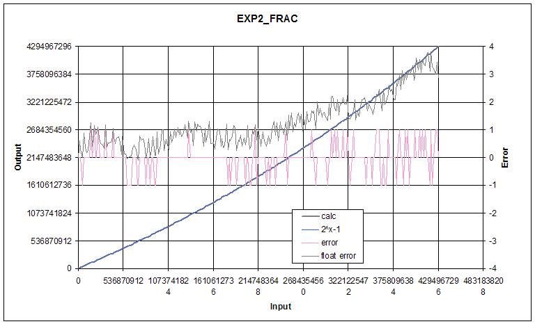
  2^x - 1 = Ax + Bx^2  + Cx^3 + Dx^4 + ...

This function is conveniently concave downward, which means there is no need to prescale the input or output to have the coefficients fit in the unsigned 32 bit space.

For a 32 bit process that employs a Hive type "extended unsigned" multiplies (i.e. the upper 32 bits of a 32 x 32 unsigned multiplication) the errors are as follows:

  one x term:   -370M
  two x terms: +/-16M
  three x terms: +/-650k
  four x terms: +/-23k
  five x terms: +/-600
  six x terms: +/-80
  seven x terms: +/-3

For 32 bit representations it seems worth going to 7 terms as the error at that point is negligible.  It might be possible to reduce the error to +/-1 as there are only a few input values that give error larger than +/1, but I ran out of patience. 

Mathematical operations are minimized by interleaving the power operations in with the coefficient operations:

  poly = Ax + Bx^2 + Cx^3 + Dx^4 + Ex^5 + Fx^6 + Gx^7
  poly = x(A + x[B + x(C + x[D + x(E + x[F + y(G)])])])

Because it is non-linear (unlike INV_F), EXP2 doesn't lend itself to linear scaling of input and output.  In addition, EXP2 presents one with the very pressing need to implement some kind of decimal place indicator for both input and output - an EXPonent - which together with the input/output value - the SIGnificand - form floating point values.  We require an input exponent because it tells us how to separate the input integer part from the fractional part for processing: the fractional part is evaluated via polynomial approximation and the input integer part forms the basis of the output exponent.  And we strongly desire an output exponent because doing the actual shifting of the result would generally toss away many bits of precision.  Implementing a float version of EXP2 is something of an algorithmic trial-by-fire, as it raises all sorts of thorny issues that must be dealt with.

The float convention that seems most natural to me is for the significand to have the decimal place to the left of the MSb.  This gives an unsigned range of [0:1).  One of the reasons it "seems most natural" is due to the fact that it is impossible for the multiplication of the significands to overflow with this arrangement, i.e. if both input values are guaranteed to be less than one then the multiplied result will always be less than one.  This arrangement also maintains maximum precision for the truncated (i.e. chopped off LSb's) multiplied result.  Since the unsigned representation has an implicit leading zero to the left of the decimal, the quantity 1 must be represented as 1/2 * 2^1, or SIG = 0b100...000 and EXP = 1.

There is a huge value in having floats fit into conventional spaces, and cleverly packed floats such as the IEEE754 - where the sign bit, biased exponent, and unsigned significand occupy a power of 2 bit width - may be conveniently arranged to undergo magnitude comparison as simple signed integers.  But there are also major disadvantages.  The packing and unpacking process is inefficient if it is not directly supported in hardware.  Worse, whatever room is reserved for the exponent has an obvious and direct negative impact on the precision of the significand, so it is impossible to represent all signed n-bit integers with an n-bit float, forcing one to go to 2n floats if that is needed.  Packed floats are a classic trade-off scenario.

The IEEE754 float specifies an implicit 1 to the left of the significand decimal point, yielding an unsigned range of [1:2) which clearly doubles the precision by adding a bit.  But the downside is that significand multiplication overflow can occur, and underflow "denorms" - where the exponent low end limit is hit and the significand is allowed to take on values less than 1 - require special handling.  I believe the implicit 1 is there mainly to make up somewhat for the loss of precision from packing, and not because it makes anything easier.  With the given input range of [1:2), the output range of a multiply is [1:4), which complicates things.

IEEE854 generalizes IEEE754 and adds an "extended precision" type where the single precision significand occupies the full 32 bit space, and the exponent presumably some fraction of a second space.  This seems geared towards processors that don't possess floating point hardware.  It only places a lower bound on the width of the exponent, so I'm using 16 bits here because it's generally easier to use a power of 2 width.

Anyway, how do we handle the input and output exponents, and how do they influence the output significand?  From the discussion above, we know how to generally handle the integer and fractional parts of the input.  The fractional part is found via polynomial approximation, and the integer part simply shifts that left:

  2^y.x = 2^(y + 0.x) = (2^y) * (2^0.x) = (2^0.x) << y

In terms of preprocessing, we have some input SIG_i and EXP_i that we have to translate into y (shift value) and 0.x (poly input value).  In terms of post processing, we need to determine EXP_o, and massage the result of the polynomial approximation a little to determine SIG_o.  Due to the float representation of the value 1 it won't be too surprising to discover a lot of +1 offsets in the EXP_o algorithm.  Note that the poly result gives 2^(0.x) - 1, and not 2^(0.x), so a poly input of 0 gives a result of 0.  We need to shift the poly result to the right once, add 0b1 (negate the MSb), and increment the exponent, which gives us the correct result of 2^0 = 1/2 * 2^1 = 1.  We also need to keep in mind that Hive shifts are signed modulo and not internally limited in any way. 

The most basic case to consider is when EXP_i is within the shift distance non-modulo limit [-32:31].  For the full range of EXP_i here, we set 0.x = SIG_i << EXP_i, which for non-negative EXP_i simultaneously left aligns the decimal portion 0.x with the implicit left decimal, and truncates away the upper integer portion y.  Performing the opposite shift (i.e. EXP_i - 32) yields the upper integer portion y right aligned, which forms the basis of EXP_o: EXP_o = [SIG_i << (EXP_i - 32)] + 1.  What about the case where EXP_i is within the modulo limits but negative?  Here there is no integer portion y, so we set EXP_o = 1 and let the right shift of SIG_i naturally denormalize 0.x towards zero.

If (EXP_i < -32) then the input is to be right shifted beyond the basic data width of 32, to zero or past, so 0.x = 0.  Since 2^0 = 1, we desire SIG_o = 0b100...000 and EXP_o = 1, which is satisfied by 0.x = 0 and EXP_o = 1.  Since the (EXP_i < 0) case is already covered above, there is no new rule needed for it here.

If (EXP_i > 31) then the input is to be left shifted beyond the basic data width of 32, which means what exactly?  Well, there can't be a fractional portion so 0.x = 0.  And with no fractional portion we are dealing purely with integer powers of 2.  In fact, EXP_o = [SIG_i << (EXP_i - 32)] + 1, just as in the basic case above.  And this works until we hit overflow.

Underflow can't happen as very small inputs denorm to zero, giving 1 as the result.  But overflow is definitely possible since we have an exponential input being exponentiated.  How do we detect overflow?  One way is to look at EXP_o and see if it exceeds the maximum.  But we can't rely on this alone due to the modulo nature of the shifting - we won't get false positives from checking EXP_o but we can get false negatives.  A method to see if we're close to overflow is to calculate how many bits EXP_o requires.  Since EXP_o = [SIG_i << (EXP_i - 32)] + 1, we need to count the bits required by the SIG_i value, which can be found via 32 - lzc(SIG_i).  Since this is shifted by EXP_i - 32 we can add the two to find the bits required: EXP_o bits = 32 - lzc(SIG_i) + EXP_i - 32, = EXP_i - lzc(SIG_i).  It is unfortunate that the EXP_o calculation has the "+1" at the end because this creates a corner case, so we must also check the actual value of EXP_o itself.

Things not covered here are negative input (which should return an inverse result), rounding, overflow signaling, etc.

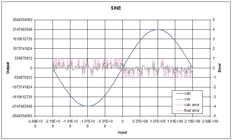
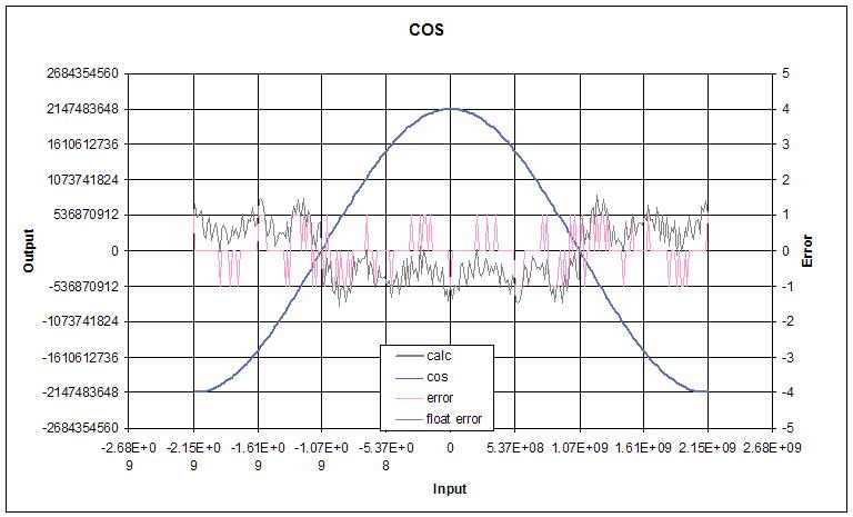
I've been wanting to do a deep dive on transcendental functions for what seems like forever, which I suppose is one of the reasons I'm dwelling so heavily on it now.  I don't know why, but it's freakily satisfying seeing a polynomial with some input conditioning return essentially the same values as Excel over the full float range.

You must be logged in to post a reply. Please log in or register for a new account.