Let's Design and Build a (mostly) Digital Theremin!

Posted: 6/22/2016 7:40:57 PM
oldtemecula

From: 60 Miles North of San Diego, CA

Joined: 10/1/2014

I made some changes in my several thousand lines of VB code and now finding it a bitch to isolate a bug. It beats the Stock Market and seems to be evolving into its own life form.

The same as I don't Model, in code I have never used a flow chart. It is all in my head and I just hack away. Where we may differ is I can demonstrate results. lol

Cowboy coding comes so easy to you, do you run code or just think up little snippets and drool over it?

Christopher

Posted: 6/23/2016 11:53:02 PM
dewster

From: Northern NJ, USA

Joined: 2/17/2012

"I made some changes in my several thousand lines of VB code and now finding it a bitch to isolate a bug." - Christopher

I've been pretty lucky with the Hive simulator code, but I did some floor planning up-front.  Structures that encapsulate functionality and data together are C++ objects.  The main memory is an obvious object, with private and public functions that read and write, copy sections, parse hal and mif files, etc.  There are 8 threads so I decided to make them objects as well, which drastically reduced redundant coding.  The core creates the memory and threads and is itself an object, so I could instantiate a multi-processor sim pretty easily.  I'm comfortable with the OO approach because it is very similar to the component approach hardware description languages employ.

But, yes, I sit around writing out small critical snippets until I feel they're pretty well nailed down before actually coding.  That makes me a slow coder, but I think I spend a lot less time tracking down bugs.  The sim code is getting a bit ungainly at this point, but I don't think I'll be adding much more to it.

VB is one of the worst languages I've used, but you're kind of forced to if you want to do anything fancy in Excel.  It's clunky, overly verbose, slow as a snail, and not very readable.  I pretty much loathe it.  C and to some extent C++ make a lot of sense to me, but some of this may be my familiarity with them.  C very clearly targets real processor hardware, and that's the best starting point for a language IMO.  C++ would benefit from a whole lot of stuff being removed, particularly most of the class and inheritance crap.  And pointers in both drive me crazy, I hate pointers and I hate the lame syntax they picked.  Pointer arithmetic is just asking for it IMO, and I think that's what makes these languages so unsafe.  If you want to indirectly reference a bunch of items instantiate them as an array.

Posted: 7/5/2016 7:37:55 PM
dewster

From: Northern NJ, USA

Joined: 2/17/2012

HCL (Hive Command Line)

Just got the command line up and running an hour or so ago.  I decided to make it as minimalist as possible, so the basic commands, which can be up to 4 characters long, only use single letters for the functions.  Parameter count is limited to none or one, with none generally signaling a read, and one a write, where the parameter value is the write value.  Addresses are handled via a separate address command, with auto increment on memory read / write.  Here is a list of the commands so far:

a : read address
<addr> a : set address
m : read memory (32 bit), addr += 2
<data> m : write memory, addr += 2
l : read memory (16 bit), addr++
<data> l : write memory, addr++
v : read version register
<data> v : write version register (no action)
t : read time/id register
<data> t : write time/id register (no action)
e : read error register
<data> e : write error register
u : read uart register
<data> u : write uart register
g : read gpio register
<data> g : write gpio register
s : read spi register
<data> s : write spi register

Commands are case sensitive.  Parameters may be entered as unsigned decimal or hex.  If an unrecognized command or malformed numeric parameter is encountered a question mark is spit out.  All responses are in hex on a new line.  Conveniences like backspace and doskey command recall are not supported.  ESC clears things out.

The framework can handle up to 32 tokens per command, and could be trivially modified to handle per-radix tokens and signed values, but I decided to KISS.

Writing to the GPIO register sets the LEDs, pretty cool stuff!  Next will implement CRC32 checking.

Programming via this interface can be done by setting the base address, then doing repeated 16 or 32 bit writes to memory.  The command line prompt '>' isn't transmitted until the individual operation is complete, so a programming script can key off that to wait / proceed.

[EDIT] Just added CRC checking.  It uses the default address as the start and end, and if there is a parameter it substitutes that as the end address.  The single value 0xdeadbeef gives a residue of 0xe5a59fe0 just like the spreadsheet says it should - sweet!  Inverting this gives 0x1a5a601f, and appending this to the first value and running the CRC check over both gives 0xdebb20e3, which is the good CRC check residue value (a constant).

One thing that's interesting here is if I put all the threads in an infinite loop except for one, then overwrite all of memory with identical code to what the active thread is running, I'm then free to overwrite the code areas that aren't being currently executed with whatever I like (provided the running code isn't using the memory for data storage).  After that it's just a matter of resetting all the threads in order to run the fresh SW load.  You can see why they call all this stuff "bootstrapping" as it takes a lot of thought to make a flexible processor start up procedure.

Posted: 7/9/2016 2:55:00 PM
dewster

From: Northern NJ, USA

Joined: 2/17/2012

Knee-deep in involuntary volunteering (and the big fool said to push on) so haven't had much time to devote to my own stuff.

This morning I made a simple Tera Term (excellent program) macro (script) which writes the ~24 lines of the bouncing ball LED program to the demo board starting at address 0x160.  It then overwrites the initial jump address for thread 0 to address 0x160, and finally overwrites a line of code that thread 0 is executing to reset the thread, which causes it to vector to the uploaded code.  It worked first time (if you don't count the first three basic tests :-) and is bouncing in front of me now.  So I'm mostly past the point of needing to recompile the HW just to run new SW.

I knew going down this road that it might take years to reach this point.  Now I have a processor with full simulator, assembly language, floating point math package, and command line interface support.  What a long strange trip it's been.  So it's back to actual Theremin hardware as soon as I can catch a break.

Posted: 7/12/2016 5:36:42 PM
dewster

From: Northern NJ, USA

Joined: 2/17/2012

NCPD

I'm taking another look at the digital generation of square waves for LC tank stimulus.  Generating a precision variable lower frequency clock from a fixed higher frequency system clock is a fascinating area of study, and one I've nosed around in quite a bit.  LC is nice because it acts like a low pass or band pass filter, thus strongly attenuating drive harmonics.  LC also acts like a flywheel, so as long as the stimulus is correct on average (i.e. over several cycles) then individual cycle stimulus can be less than ideal - which it will be because we only have discrete system clock periods with which to construct the output cycles - the output transition points are fixed so they usually won't correspond exactly with the desired transition points.

The general approach is that of the phase accumulator or NCO (numerically controlled oscillator).  Take an input number and on each system clock add it to a fixed width accumulator.  The larger the input number the more often the accumulator will roll over.  The MSb (most significant bit) of the accumulator is a square wave clock with frequency

  clk_o = clk_i * freq_i / 2^n 

where clk_i is the system clock, freq_i is the input number, and n is the bit width of the accumulator.  The precision with which we can set the output frequency is set by the accumulator width, and it's fairly trivial to get PPM resolution just by using 20 or more bits.  Lower frequencies can be accommodated with an integer divider afterward, which enables a decoupling of the carry chain for speed up.

The output will be best-effort in terms of phase error from the ideal.  That is, the nearest system clock edge is used as the output clock edge.  This may sound ideal, but in most cases it actually isn't because the output phase error can easily form low frequency alias patterns (limit cycles) that are impossible to deal with via filtering, even in our LC case.   One way to break up patterns is to permanently set the LSb of freq_i to a 1, which keeps the lower bits of the accumulator active, and provides ~3dB SFDR improvement (spurious free dynamic range is the figure of merit here).  An even more effective technique is to take the parallel output of the accumulator, add a small amount of dither noise (peak average amplitude >= than the value of freq_i) and use the MSb of this as the output square wave.  Each new output edge triggers the noise generator to provide a new noise sample.  Conceptually, what is happening here is we are statistically exposing the full accumulator value to the world.  Using this technique one can produce square waves with high spectral purity, certainly with enough quality for digital Theremin use.  Indeed this is exactly what my first prototype employed, in a DPLL configuration where the phase error was measured and used as feedback to adjust the frequency / phase.

So why look this dithered, LSb=1 style NCO gift horse in the mouth? 

Well, one issue is the freq_i input is accumulated on every clock.  This can be an asset, because variations in freq_i are then averaged over the entire cycle (this is a form of moving average or boxcar filter).  But it also means this small number gets multiplied up by a factor of clk_i / clk_o, so if we are generating freq_i from a control process like the accumulator or low pass filter of a DPLL, it must be highly attenuated before use, which tends to throw away precision in the digital realm.  Another issue is the dither noise should ideally vary between zero and the value of freq_i, which requires either multiplication, or the employ of a somewhat non-ideal fixed and larger noise level (though there are tricky and efficient ways to do the multiplication via a series of adds).  A final issue is that we measure things like phase error by counting system clocks, which are therefore period rather than frequency based, which gives us a variable loop gain factor to worry about.  It would be more direct if we could control the period numerically, rather than the frequency.  How might we do that?

The obvious approach to a NCPD (numerically controlled periodic delay - my term for it) is to take the input period_i and count up to it from one, or load it into a counter and count down to 1.  But how do we handle fractional periods, where e.g. period_i = 9.125?  We could accumulate the fractional portions until the sum is >= 1 then extend the output period by 1 system clock and subtract 1 from the accumulator.  This approach works but it is a bit fiddly if implemented as two parts.  It gets even fiddlier if we dither it, and we definitely want to do so.  Is there any way to more tightly integrate things?

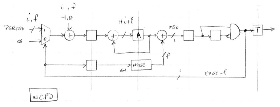
The above diagram shows where I am at the moment with a solution.  The input is a fixed decimal with i integer bits and f fractional bits.  This gets selected for one clock at each output clock edge, which adds the value, with the integer 1.0 subtracted from it, to the accumulator A.  The rest of the time an input of zero is used, which gives us -1.0 as the input accumulator value, which decrements the integer portion of the accumulator value and leaves the fractional portion undisturbed.  After this, noise is added and the MSb of the result is registered and the rising edge detected.  This flag is used to toggle the output, to control the input multiplexer, and to generate a new dither noise sample.

What's so clever about it?  First, the accumulator holds both the integer and fractional values, which lets the accumulated fractional portion naturally carry out into the integer portion.  Second, it's a closed-loop "leaky bucket" implementation, so the input accumulation can happen at just about any point and it will still function correctly long-term, which allows us to perturb an individual period without affecting the next, we can employ roll under detection (MSb going from zero to 1) to sense when to accumulate period_i, and we can inject noise without slowing things down.  Third, the optimal dither noise width is fixed (the same bit width as the accumulator fractional width) so we don't need multiplication in order to scale it.  Fourth, there is a bit of magic that can be applied to the noise generator which gives us an approximately differentiated output with one clock per sample almost for free (I'll describe this in a future post).

Using a fairly deep pipeline here really speeds things up (>300MHz system clock limited to max 250MHz net toggle rate in the target device).  It also limits the smallest input period value, though that doesn't really matter as we will be using the NCPD to synthesize square waves with many tens of system clocks per period.

Posted: 7/12/2016 7:29:33 PM
oldtemecula

From: 60 Miles North of San Diego, CA

Joined: 10/1/2014

dewster said: "clk_o = clk_i * freq_i / 2^n "

What dew is trying to figure out is how to beat latency or better yet out run time.

Christopher

Posted: 7/13/2016 3:15:44 PM
dewster

From: Northern NJ, USA

Joined: 2/17/2012

Dithering

As I pointed out above, dithering is used to statistically expose the least significant portion of a value (to the world downstream) which would normally get simply truncated.  Lopping off the lower bits can obviously produce truncation noise, and this is the reason the final step in CD mastering (before truncation) is the application of dither.  Without dither, if the the volume is turned up during a very low passage (e.g. song fade out), the listener will hear increasing distortion with decreasing loudness.  With dither, the perceived distortion will be vastly lowered, and the listener will be able to clearly hear audio information below the noise floor.  It seems a little like magic, but it is actually a slight increase in one kind of noise (dither) that leads directly to better performance by reducing a worse kind of noise (truncation).  The dither noise may be straight white, or shaped.  The important features are that it have sufficient amplitude to expose all truncated values (+/- 1/2 bit post truncation), and that the waveform represent all values equally over some time interval (for the statistics to work).  Having minimal energy near DC may also be important for some applications.

As an example, say we have a 24 bit value IN[23:0] that we need to reduce to 16 bits OUT[15:0].  The difference in width here is 8, so we would apply dither DITH[7:0] to IN[23:0] via addition and get RESULT[23:0], to which we would then truncate off the bottom 8 bits to get RESULT[23:8], and this then is OUT[15:0].

It's easiest for me to think of IN[23:0] as a fixed decimal: IN[23:0] = HI[15:0].LO[7:0] (and I often wish hardware description languages allowed for the use of negative bit indices so that the decimal portion could be expressed as LO[-1:-8]).  So a value near the noise floor such as 12.5 would have a 50/50 chance of being dithered and then truncated to 12 or 13.  The fractional portion directly dictates the probability of the integer portion being bumped up one.

It might seem that the dither signal could be injected anywhere, but this generally isn't the case.  Filtering or accumulating the signal in any way will alter the statistics of it (averaging white noise gives you a Gaussian distribution), rendering it less useful at reducing truncation noise - or perhaps worse, emphasizing low frequency content in the dither signal itself.  So we shouldn't e.g. combine dither noise with freq_i at the input to an NCO.

In practice, the dither signal can often be unsigned, even if we are working with signed values.

Posted: 7/17/2016 3:13:24 AM
dewster

From: Northern NJ, USA

Joined: 2/17/2012

Hanging out at hacker news a lot (hey, it beats working!) and ran into the term "technical debt" a few days ago.  I suppose I'm so averse to it that I spend what some might deem too much time polishing hardware description code for prototype use, but even my polished stuff often seems too crude to me.  The trouble with polishing up-front is you spend less time with a functioning prototype, but the the problem with not polishing up-front is you spend weeks or months tracking down the simplest of bugs, only to feel stupid and relieved after you find them.  To me, debugging boners is zero fun, but deeply understanding each part of the whole is quite enjoyable - and I've got no boss with a bogus timeline breathing down my neck.  Is anything good or lasting ever done in haste?

Posted: 7/17/2016 4:28:41 AM
oldtemecula

From: 60 Miles North of San Diego, CA

Joined: 10/1/2014

dewster said: you spend weeks or months tracking down the simplest of bugs, only to feel stupid and relieved after you find them.

I found my bug after a few days. Programming is made up of thousands of little routines and then to find a bug I must relearn what was I thinking in each section of execution. Once smoothed out there is an ah-ha moment almost orgasmic.

dew the theremin culture interest has changed and I feel myself fading, I wish you the best.

Christopher

Posted: 7/17/2016 6:25:54 PM
dewster

From: Northern NJ, USA

Joined: 2/17/2012

LFSRs & "Free" Logical Differentiation

A fascinating digital construct is the Linear Feedback Shift Register.  Using a shift register (string of flops), a two or four input xor gate (depending on the shift register length), and judicious choice of stages for the feedback, one can produce sequences that are "maximal length" or 2^n - 1; one less than the states of a binary counter of the same width.  The output can be taken serially from one flop, or in parallel from the entire string or some some subset of it.  Because the feedback is so simple, such constructs can be used as jumbled counters that run at extremely high speeds, though they are most useful as sources of pseudo-random noise.  The "pseudo" here is because the noise has many properties of a true random number generator, but is entirely deterministic.  Two such noise generators combined with another xor gate form a Gold Code generator which is used to allow many cell phones to use the same frequency, and deterministic noise has obvious data encryption uses, but I digress.

Where I'm going with this is we need a source of dither for our NCPD above.  Say the LC resonance is nominally 2MHz, this gives us an "edge rate" of 4MHz, so we need a new noise sample every 4MHz.  Say the period fraction (the portion that needs to be dithered) is 16 bits wide.  There are a couple of options:

1. Run the shift register for 16 clocks for each output edge in order to get a new, relatively unrelated 16 bit noise sample for each edge.  The minimum system clock required would then be 4MHz * 16 = 64MHz.  So as not to have humans easily detect the repetition of the sequence, we set the period to many seconds.  Since 64M ~= 2^26, 26 flops give us a one second period, and we set the shift register to 29 flops to get 8 seconds of noise samples before repeating.  We could easily set it longer, the addition of each inexpensive flop doubles the period and has no impact on the speed.  If the shift register is sr[28:0], then the LFSR output is sr[15:0].  If we want to kill the DC of these noise samples we simply differentiate the output. 

2. The second option is quite tricky and one that's taken me some time to wrap my brain around.  Say we're lazy, or don't have the real-time to generate a full 16 bits of new noise for each output edge, so we simply clock the LFSR once for each output edge, and differentiate the output in order to scramble it a bit and kill DC.  On a whim we look at the outputs of the LFSR and differentiator and discover they're virtually identical!  This is because a single shift of the LFSR multiplies the old output by 2 and adds either 0 or 1 depending on the feedback value, so output values are highly correlated (related to each other).  If the old output was n, then the new output is 2n or 2n +1.  Differentiating this gives 2n - n = n (+0|1), which is pretty much the old value, so the undifferentiated output is in some sense already differentiated.  The key is examining the behavior at the modulo points.  A one shifting up through a field of 8 zeros gives:

0 1 2 4 8 16 32 64 128 0 ...

Differentiated:

0 1 1 2 4 8 16 32 64 -128 ...

So we can simply invert the MSb to get "free" first order differentiation.  If you do this exercise in a spreadsheet you'll see a somewhat tilted up at zero spectra for the one-clock per sample LFSR output, which becomes somewhat tilted down when the MSb is inverted.  And the effect is more pronounced for higher bit widths, presumably because the feedback error "noise" bit (deviation from true differentiation) is smaller compared to the maximum value.

You can do this kind of free "logical differentiation" to as many orders as you wish, but it leaves large gaps in the output values above first order.  I've derived the logic via observation and tested it to third order, and it's almost eerie watching it work.  First order is nice because it still gives you the full range of values to work with.

Credit to U.S. Patent US7580157 "High-pass dither generator and method" for the above, and it unfortunately has many years before expiration.  The patent also covers conventional differentiation of noise, which doesn't strike me as novel in the least.  The patent doesn't seem to cover higher order logical differentiation, so I may have thought of it first but I'm not about to patent it (and IANAL).

My spreadsheet: http://www.mediafire.com/download/twd99yb1yn28wvt/lfsr_logical_diff_2015-10-22.xls

[EDIT] I should add that there is a third option, one I've tried in the prototype (so I know it works for the NCO): simply run the LFSR continuously.  To restore the repeat period to several seconds the shift register will likely require extension by a few flops, but this is inconsequential.  The dither circuitry may need slight alteration to accommodate the continuously changing noise without error.

You must be logged in to post a reply. Please log in or register for a new account.