


Congratulations on your top view TW thread. What... was it about?

Thanks, but it's not the top view thread (yet), this one is for some reason:
http://www.thereminworld.com/Forums/T/28802/new-entry-for-moog-halloween-competition
Going off camping with the family for the weekend, will continue hardware integration on return.
Pushbutton Debouncing
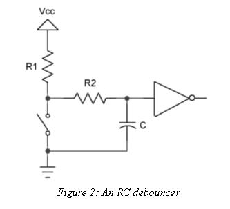
Interfacing logic with an SPST pushbutton is more complex than it seems (these are the types of switches in typical rotary encoders when you press on the shaft). Switches like this tend to "bounce" or make and break several times when closed, and can take a while to float back up to VCC when opened (via a pull-up resistor) which can produce multiple logical threshold transitions due to noise. One method here is to put a capacitor across the switch, which is quickly discharged via the first bounce, and which "holds" the state during subsequent bounces. This tends to slow down the float back up, and discharging a cap directly like this can prematurely wear out the switch contacts.
One way I've done this in the past is to have a "stability detector" which is just a counter and an edge detector. When an input change is detected the counter is reset, if the counter reaches maximum the output is set to the input. If you think about it you don't even have to stop the counter at max. One problem with this method is "tuning" or making sure the timing interval is long enough to catch all bounce and noise events, but not so long that reaction to the switch state feels sluggish or delayed to the user.
I'm still thinking about it (there is the possibility of driving the other side of the switch and detecting "transmission" through it) but it's probably best to have software more involved in the detection of switch events so that they can be more flexible, and any changes in state can be responded to in real-time. It's not enough to simply sample the switch state every here and there and really know what's happened between samples (an aliasing issue, actually) so two bits could be provided for each switch: one read bit that indicates the current switch state, and one clear-on-read bit that indicates state change since the last sampling point.
Now the classic 555 is known for this sort of thing but you want minimal parts! What is the word I am looking for "hysteresis" or hysterectomy? 0-'
Christopher
Thanks Christopher. This is a good application for hysteresis, and the whole RC low-pass thing is also good as it would tend to roll things off above 2kHz here, so the Theremin pitch and volume fields probably wouldn't cause it to switch. But I wonder if shorting out that 10nF every time the button is pressed would decrease the lifetime of the switch by wearing out the contacts? An extra series resistor seems called for (from: http://www.ganssle.com/debouncing-pt2.htm):
The Theremin presents one with a rather harsh EMI scenario, so extra caution is likely called for. For the rotary encoders I'm hoping gray code state tracking will be enough.
[EDIT] I just hooked the pushbutton output of a rotary encoder up to a 1k pull-up and examined it with my scope. No matter what I did I couldn't get it to bounce when closing the contact. Opening the contact would occasionally give a bounce though. These are well-behaved switches.
Lies My Datasheet Told Me*
Back from vacation and spending some quality time with the LCD module / Hive serial command line interface / TeraTerm scripts. Things I've learned today:
1. The display powers-up in 8-bit data, 1-line, 5x8 pixel mode, display OFF. After powering up the LCD and adjusting the contrast, I notice the first and third lines have all the pixels activated to a light gray. This is 1-line display mode, and the light gray can be adjusted out with the contrast control. (Note that the controller line count is different than the actual display line count: most modules, even most single line ones surprisingly, require the controller to be in two line mode, presumably for the lowest electrical multiplexing ratio, and therefore the best contrast.)
2. After hardware reset (power cycle) it is only necessary to issue a single Function Set command (binary 0010,1xxx) in order to set the interface width (4-bit data and 2-line mode here). After issuing this command the first and third line light gray pixels above turn off completely and the display is blank - I believe this difference in contrast is due to the change in electrical multiplexing between the 1-line and 2-line modes.
3. Issuing a Display Clear command (binary 0000,0001) also resets the cursor position to address zero. This is consistent with the datasheet.
4. 5x10 font mode is not supported in 2-line mode. It is supported in 1-line mode. This is consistent with the datasheet.
5. The controller datasheet makes a huge deal about the funky Software Reset procedure, and says that after issuing a Function Set command "...the number of display lines and character font cannot be changed afterwards." But I'm not seeing this at all! I can freely set the display lines, the font, and the data width at any point and the controller responds accordingly. Because of the this, the much ballyhooed Software Reset sequence seems to be essentially meaningless? Things you can't change once set without going around your ass to get to your elbow merit extreme caution, but I'm just not seeing it here.
6. I believe you can always send full bytes as two nibbles, even for things the datasheet says to send as a single nibble (i.e. the Software Reset cha-cha). This alone is worth all of the investigation I've done, as it simplifies the hardware interface considerably.
So here is the minimal start-up command sequence (the MSb here is the inverse of the RS bit sent to the module, 1=command):
This seems to be the default and therefore optional, but I would do it just to be safe:
0x106 // Entry Mode: increment address, no shift
I'm only testing a single modern part (SPLC780 is the controller EastRising points to for this module) and could be that they've cleaned up the controller behavior somewhat since the early days and neglected to update the documentation, or this is the wrong document for the part on the board, or perhaps there are variations out there which behave differently (lots of manufacturers seem to make this part) - who knows? But, even though it has pretty terrible timing at the interface, this one isn't nearly as squirrely in terms of reset, mode switching, and nibble demands as the datasheet would certainly lead one to believe. Datasheets that deceive in this way are the worst IMO because they can lead to all kinds of superfluous / superstitious thought and activity surrounding the part. A datasheet should give you a very clear picture of what you should and should not do at the interface in order to get the behavior you expect.
* A riff on the movie titles "Lies My <Father|Mother> Told Me".
Pushbutton Debouncing (cont.)
Following up on some vacation circuit doodling. If you think about it there are two separate things going on with pushbutton conditioning. 1: The first thing is dealing with the high impedance state of the open switch - high impedances invite EMI or RF interference to confound things. 2: The second is debouncing, or deciding what state the switch is in in the presence of contact bounce. I believe the first is best dealt with in the analog domain. The second will likely be improved somewhat as a side effect of dealing with the first, but the time constants required to fully cover the worst-case debounce interval can be orders of magnitude longer and require tuning, so they might best be dealt with in the digital / software domain.
As Christopher noted, squashing RF can be done with an RC network, and a second resistor should be used to limit current inrush through the switch in order to protect the contacts long-term. So three passives per switch minimum. The RC forms a kind of integrator that low pass filters RF and also pulls up the open switch. Playing with the resistor values one can make both integration times roughly equal, or the open=>closed integration time much shorter.
RC isn't the only game in town, I was thinking one could employ dual current mirrors to pull the capacitor around in a linear ramping fashion:
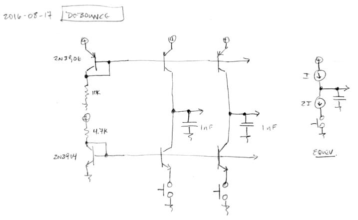
The transistors on the left are diode connected, and using them to bias the transistors on the right creates dual current mirror arrays which pull to VCC and ground. The resistors are sized to give roughly double the pull-down current, so the net result is the capacitor "sees" the same current whether ramping up or down (pull-up current is ~1/4 mA, pull-down ~1/2 mA, and clearly 1/2 - 1/4 = 1/4). An equivalent representation is shown on the right. The two diode connected transistors can bias many transistors to the right.
When no buttons are pushed there is no current flowing in any of the transistors except for the two diode connected ones. Each switch requires two transistors and a capacitor. With the above values and a 3.3V supply I'm seeing ~12us fall time when the button is pressed, and the same ~12 us rise time when the button is released. Occasionally the rise time can be as long as 100us. These are pretty clean switches.
It might seem excessive to devote two transistors to each pushbutton, but it's a pretty clean setup. I can inject a 24Vp-p 1MHz sine wave into the 1nF via a series 10pF cap and the interference doesn't look very significant on the scope (maybe 0.3Vp-p). I don't think the Theremin environment will be quite that harsh, but if it is the R's and C's can be adjusted accordingly.
Set-Reset bistable latches can also be used as Monostable (one-shot) pulse generators to generate a single output pulse, either high or low, of some specified width or time period for timing or control purposes. The 74LS279 is a Quad SR Bistable Latch IC, which contains four individual NAND type bistable’s within a single chip enabling switch debounce or monostable/astable clock circuits to be easily constructed.

Edit: From my experience you can never be certain a normally closed push button switch will make proper contact every time upon release, it can stay open.
Yes, and you can describe the same structure in FPGA fabric. I'd definitely go that route (or a clocked version of it - always use a common clock if you can as the outputs will integrate better with the rest of the design) if the pushbutton were SPDT rather than SPST. The essentially zero / infinite impedance of the two SPST states is a real problem - it might actually be easier to deal with NC (normally closed) rather than NO (normally open) SPST due to EMI issues - I suppose they make all the contacts in rotary encoders NO so that they won't draw power when just sitting there.
It's Clobberin' Solderin' Time!
Started wiring up the LED tuner yesterday, finished it this morning, and finished testing it a few minutes ago:
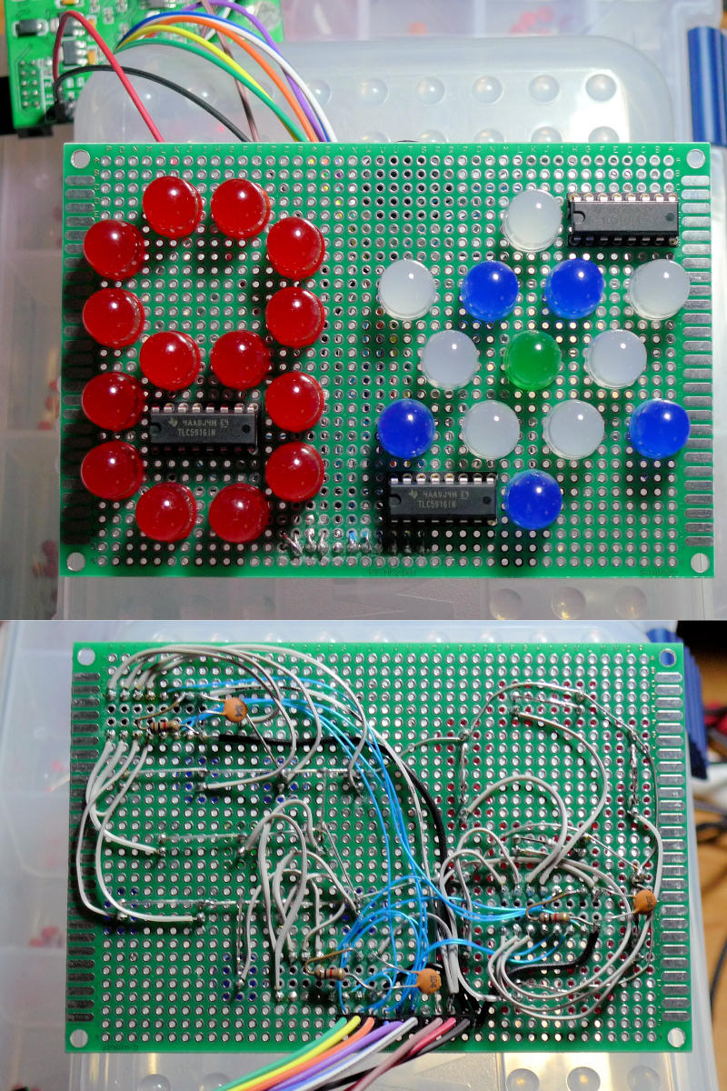
These are front (above) and back (below) views. It uses three TLC5916 chips, and is controlled via a special serializer construct connected to the Hive register set (described in a previous post). The Hive demo board is connected via those colored wire jumpers and can be seen above left.
OMG wiring is lots of work, I'd much rather be coding! A bottle of liquid rosin flux is your best friend when doing this kind of thing. Make sure you use a high quality plated-through fiberglass epoxy (FR4) prototyping board, and good machined sockets for the ICs. I used wire wrap wire for the digital signals, separated floppy ribbon cable wire for the 3.3V supply and LED drive connections, and bus wire for the grounds and 5V supply connections. The clock and latch enable are wired in a star pattern from the pin header for best signal integrity.
I wrote a register access subroutine called 'f' for the Hive command line interface, and exercised the register via a TTL script. Lit each LED, did some patterns and some 7-segment decoding, tested the current drive settings. It all works fine, no surprises (thank goodness).
The final one will likely be surface mount, with the ICs mounted on the other side, and some kind of black mask or black spray paint for the background so as not to distract from the LEDs. Some smokey Plexiglas or acrylic sheet in front to further heighten contrast.
I'd post a video of it operating with the script, but it's pretty dull as there's no PWM going on, just blinky stuff. The plan is for the real software to do PWM at the audio sample rate (48 kHz).
You must be logged in to post a reply. Please log in or register for a new account.
