Let's Design and Build a (mostly) Digital Theremin!

Posted: 1/20/2017 5:39:59 PM
dewster

From: Northern NJ, USA

Joined: 2/17/2012

Since it's working so well, I decided to transfer the volume side 2mH coil over to the pitch side, and cut down one of the other coils I had laying around the bench for the volume side:

The coil I cut down was a counter wound double, with each section around 3.8mH and 47 Ohms DCR.  So the volume side is now running around 730kHz, and the pitch side around 930 kHz.  When I put my hand on the pitch antenna I see some small pulling of the frequency on the volume side, but nothing similar on the pitch side when I put my hand on the volume antenna.  So a 2:1 inductor sizing with the pitch frequency above the volume frequency should work fine.  This is actually what the Theremini does IIRC.

With the antenna portion of this project seemingly fairly well nailed down, and I can finally move on to getting the FPGA board off my desk and properly stuffed into the control box.  I'm quite anxious to get this baby off the ground.

Posted: 1/20/2017 10:35:53 PM
RS Theremin

From: 60 mi. N of San Diego CA

Joined: 2/15/2005

After many years of diabetes the only medications that work for me today make me very shaky, I can hardly use a keyboard, just the backspace key, then watching me solder a wire is really funny and my memory does not know what I was working on the previous week. 

Then a miracle happened this week, dewster presented something I almost understood again. I always said the ideal theremin pitch frequency was the birthday of Michael Faraday, which is 9-22, and dew missed it by 8 Hz in his post above, coincidence?  (930 kHz)

Valerie - thank you for the kind words.

ILYA - in your interesting robot linearity experiments have you compared 286 kHz against 1 MHz.

Never far away 

Christopher

Posted: 1/21/2017 9:54:39 PM
dewster

From: Northern NJ, USA

Joined: 2/17/2012

Christopher, I was starting to worry about you.  So sorry to hear about your troubles, diabetes can be a real bitch.

Posted: 1/21/2017 10:11:14 PM
dewster

From: Northern NJ, USA

Joined: 2/17/2012

DPLL & DDR

I previously instantiated DDR (Dual Data Rate) FPGA elements at the inputs to the pitch and volume DPLL phase detectors.  Today I similarly instantiated DDR FPGA elements at the outputs of the DPLL NCOs (apologies for the poor quality of the figure below, it's just a scan of my notebook scribbling):


At top is the DDR_O element functional equvalent, where two inputs are sampled on different edges of the clock and the result selected via the clock phase, which provides a doubling of the data rate.

At bottom is the NCO, where the input frequency value is accumulated and the dither noise is added.  The accommodation of the DDR_O element follows, where 1/2 of the input frequency value is subtracted from the dithered accumulator value, which gives us 1/2 bit resolution.  This is fed to the DDR output stage.

I'm not seeing tons of improvement, but I think it's probably worth the effort to do everything one can to to get the effective NCO clock as high as possible, which in this case is nearly 400MHz at both the inputs and outputs connected to the LC tanks.

============

There's a bit more interaction than I'd like at the volume side when I put my hand on the pitch antenna, so down the road I may put a bit more separation between their operating point frequencies by adjusting their inductances.

Yesterday I got the FPGA board, power split-out board, and Altera USBBlaster installed in the control box - now I just need to wire it up.  Fingers crossed that the pitch display PWM hash doesn't mess with the antennas too much.

Posted: 1/22/2017 4:57:06 PM
ILYA

From: Theremin Motherland

Joined: 11/13/2005

Welcome back, Christopher,
hope hearing your new theremin sounds again! No difference 1MHz vs 286 kHz in clear capacitance  measurements. But it will be important in the particular theremin design. I am going soon to simulate the different theremin topologies using my data.


dewster,

did you noticing the effect of a shortcircuited turn caused by solid electrode located near the coil ?


Posted: 1/22/2017 7:32:56 PM
dewster

From: Northern NJ, USA

Joined: 2/17/2012

"did you noticing the effect of a shortcircuited turn caused by solid electrode located near the coil?"  - ILYA

Hmm, I hadn't considered that!  I just figured the plate was oscillating at the same peak to peak voltage, so what's the harm of sticking the plate there?  The plates are ~15mm away on the pitch side, ~20mm away on the volume side.

OK, I just did a quick experiment:  I put an extra ~15mm spacer between the pitch coil and the plate.  The operating point went from 955kHz to 932kHz, and the voltage swing at the capacitive divider went from 2.4Vp-p to 2.9Vp-p.  So it seems the plate is acting like big a shorted turn and the coil should be kept some distance away from it.

Thanks a ton for pointing that out ILYA!

Posted: 1/22/2017 8:21:10 PM
dewster

From: Northern NJ, USA

Joined: 2/17/2012

Today I wired up the FPGA board (at bottom center right) and power distribution/SPDIF/FLASH board (bottom center left) to the (right to left:) LED tuner, LCD display, and rotary encoder boards:

Gobs o' jumper wires!  I bought some of those ribbon cables off eBay and pulled them apart to make singles.  Kinda scary as one false move could blow the FPGA board and set me back a month or so (shipping time from China).

I decided to run the LCD backlight off of the FPGA board regulated 3.3V, and it's drawing around 16mA.  I was going to run it off of one of the unused LED tuner channels, where it would draw power from the 5V rail and I could adjust the brightness in software via PWM, but thought that might generate noise.  Perhaps down the road.  I don't like drawing from the FPGA board regulator because it isn't sufficiently heatsinked for higher currents.

That's the Altera USB Blaster at the upper right, it pumps up the FPGA board.  And the thin black SPDIF optical cable can be seen at the lower left.

These translucent Sterelite (shoe?) boxes are really great to prototype in: no trouble making holes, no need for display bezels and the like, and they open and close easily for quick adjustments.

Now it's time to verify that the hardware is connected correctly and still works.  The oscillators are running, the LCD backlight lights and the contrast control works, and no smoke.  I'm powering it via the USB RS232 cable and a 2 meter USB3 extender cable I got off Amazon (should have got the USB2 3m cable).

Posted: 1/28/2017 12:30:45 AM
dewster

From: Northern NJ, USA

Joined: 2/17/2012

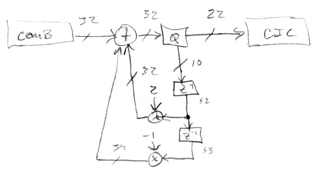
Via snippets of Hive assembly, I've verified that all the hardware is functional.  

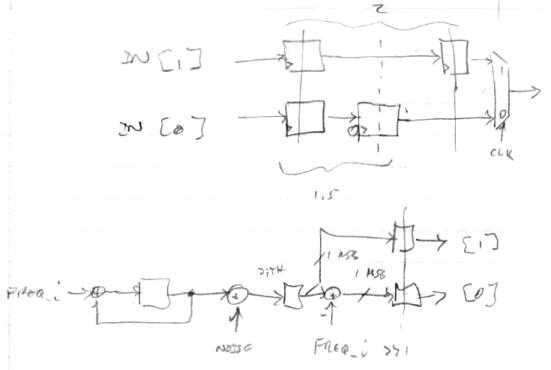
The digital conditioning of the rotary encoders in particular is interesting: I take the clockwise and counterclockwise inputs, resync them (shift registers), and invert them.  This gives a two bit Gray code, which I convert to a two bit binary code via XOR.  From there it's easy to check for the next clockwise state (+1) or counterclockwise state (-1), with full count up or down from and to the detent state causing a corresponding clear-on-read bit to light up in the Hive encoder register.  It works really well, I don't see any glitching or missed rotation events.  The carry chain is often your most efficient decode.  Each pushbutton on each encoder is similarly given a clear-on-read delta bit for when it changes, as well as a bit that is lit as long as it is pressed.  The pushbuttons do show a bit of bouncing, but very little as these things go.

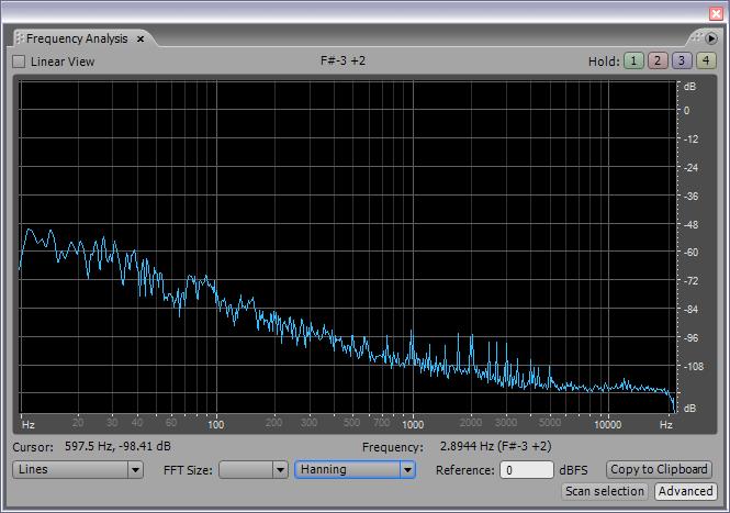
I'm seeing what is probably USB 5V droop at the LED tuner, with the red octave LEDs in series (1.7V * 2 = 3.4V) most affected by being modulated with gross circular note display activity.  Not sure how important this is.  I don't see a lot of pitch oscillator disturbance with the note LEDs cycling, but I do see some with the octave digits, which is understandable.  Not sure how important this is either.

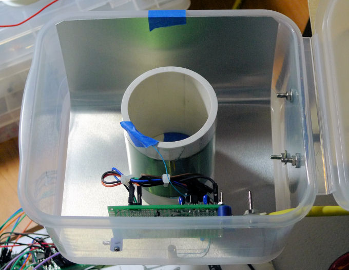
I stuck a power toggle switch on the side of the control case so I wouldn't wear out the USB connection power cycling it.  I also ordered a 3 meter USB2 extension cable which should arrive tomorrow.

===========

Today I investigated the use of the approximation d = 1/C for Theremin pitch and volume values in an Excel spreadsheet.

Working backwards from the LC resonance equation:

  F = 1 / [ 2 * pi * sqrt( L * C ) ]

Substituting in d = 1/C, Cinf as the antenna intrinsic C, and Kc as the "gain" of the hand capacitance with distance, we get:

  d ~= F^2 * 4 * pi^2 * L * Kc / [ 1 - ( F^2 * 4 * pi^2 * L * Cinf ) ]

If: 

  K1 = 4 * pi^2 * L * Kc

and 

  K2 =  4 * pi^2 * L * Cinf

we get the form:

  d ~= F^2 * K1 / [ 1 - ( F^2 * K2 ) ]

Multiplying through by K2, and setting K3 = K1 / K2, we get:

  d ~= F^2 * K3 / ( K2 - F^2 )

Clearly, K2 will be set to be a bit larger than F^2 when standing away from the Theremin.  And K3 is a general gain factor.

To get an operating point number that gets larger as the hand approaches the pitch antenna, we subtract d from a number that is the value of d when we are standing at the playing position with our pitch hand retracted.  To generalize this we can make K3 negative, which makes d negative, so we simply add d to this new factor.  What is the form of this new factor?  We want changes to a new control K4 to translate or move the entire response up and down, so it is an offset.  We also want changes to the gain control K3 to "rotate" the response about some middle point without translation.  This gives independent control over playing range and sensitivity.  With a negative K3, the graph of the line is negative sloping from zero, so we want to pull the line up to the origin at the middle point, and this is accomplished by adding -K3 * K4 (i.e. by adding a scaled translation value) to the response.  The final translation up is simply adding K4:

  translation factor = -K3 * K4 + K4 = K4 * ( 1 - K3 )

So the final form is:

  Pitch (linear) = [ F^2 * K3 / ( K2 - F^2 ) ] + [ K4 * ( 1 - K3 ) ]

Which we can feed directly to a linear response pitch display and to an exponential response oscillator or NCO.

Interestingly, with proper adjustments to everything, linearity doesn't seem to be affected by the removal of F^2 from the numerator.  But having it there probably helps normalize things.

Also, the above will work for the volume side, where we want the volume number increasing as we withdraw our hand, by simply making K3 positive and K4 negative.

Posted: 2/4/2017 12:35:43 AM
dewster

From: Northern NJ, USA

Joined: 2/17/2012

Found a small bug in LC DPLL parameter calculations which was causing the overall gain to change quite a bit depending on certain settings.  Fixed it and now the gain of the pitch number is pretty much the same regardless of how I configure the LC DPLL FPGA hardware.  This has allowed me to easily experiment with the various settings associated with data widths, cutoff frequencies, and dither generation methods and amplitude.  

And somewhat surprisingly none of the settings do all that much to make things worse or better.  Setting the phase bandwidth the DPLL loop itself lower of course improves things by removing noise along with signal (responsiveness), and there are minor improvements to the faint aliasing I'm hearing in the noise floor, as well as to the minor noise increases around those aliasing points, but it's real diminishing returns territory.  The dither amplitude max is set to that of the input frequency number, and the frequency input number has the LSb set to '1', both of which are normally ideal for a square wave NCO, and seems to be pretty much ideal in this case too.

So the above is what I'm seeing via SPDIF, and this is a second order HW/SW CIC to downsample, a first order CIC to kill mains hum, an 8th order low pass filter set to around 175Hz, and a fourth order high pass filter set to around 3Hz (the final high pass is only there to make the SPDIF signal AC for these diagnostics, and won't be in the final signal chain).

Posted: 2/6/2017 10:14:00 PM
dewster

From: Northern NJ, USA

Joined: 2/17/2012

Truncation Noise

The CIC filter I'm using to kill mains hum has a gain of 48kHz / 60 Hz = 800.  I'm feeding it 32 bit values from the HW/SW CIC downsampler (decimator) and to keep things from overflowing in the hum filter I'm shifting its input data to the right 10 places, which is the same as dividing by 1024.  This is truncation, which can produce noise and other SNR issues.  Whenever you're throwing energy away bad things tend to happen.

Papers on digital filtering, delta sigma modulation, and digital sine wave generation all deal with truncation noise by taking the truncated energy, filtering it, and feeding it back so it eventually escapes the system.  The filtering here doesn't affect the signal going through, though it does "shape" the truncation noise spectra to be more optimal.

So I took the standard form of the truncation filter, created a Hive subroutine, and placed it immediately before the hum filter:

Above is how truncation is often done.  The input in this case is from the output of the decimator comb, and this goes to a summing node.  The 32 bit output of the summing node enters the Q block where it is truncated, the upper 22 bits are shifted down 10 bits to accomplish the hum filter input attenuation requirement, and this is fed to the CIC hum filter.  The lower 10 bits that were truncated in the Q block are fed to a simple filter.  The filter consists of two delay taps with two coefficients, both of which feed back to the summing node.  The coefficients are trivial multiplies, the first is 2, the second is -1.  Note that the sum of the coefficients is 1, so there is no net gain effect.  All of the operations above are unsigned because we're dealing with unsigned input and output data.  ("S2" and "S3" in the diagram are the Hive hybrid stacks/registers I'm using in the subroutine to temporarily hold the delay tap values.)

Here is the result of me bringing my hand slowly towards the pitch antenna, then slowly retracting it (operating point high pass filtered to remove DC, fed to SPDIF):

All of the faint aliasing I was hearing in the mid field (a tone lowering to 0Hz then raising back up) is totally absent now.  I'm listening through headphones with the volume all the way up (don't try this at home!) and the center portion (where my hand is closest to the antenna) just sounds like a very distant storm (no tones).

DSP is fun once you get the hang of it!  But it's a bit of a pain getting to that point...

You must be logged in to post a reply. Please log in or register for a new account.