Let's Design and Build a (mostly) Digital Theremin!

Posted: 10/24/2018 9:26:35 PM
dewster

From: Northern NJ, USA

Joined: 2/17/2012

Noise II

I'm re-reading Dattorro's excellent "Effects Design Part 3" paper in the course of taking another look at the LC oscillator dither generators.  I realize now that my previous post on audio noise generation [LINK] has a glaring error, and I'd like to address that now.  I made a spreadsheet (noise_2018-10-23.xls) if you want to really see what's going on and maybe play with it a little: [LINK].  Some notes from that:

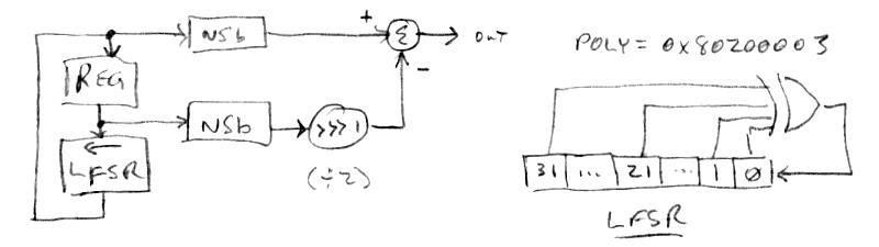
For computation, we want the whitest noise as fast as possible, and the most efficient algorithm I've run across is this one.  The simplest way to do this is take the parallel output vector (bits) from a (generally wider) LFSR (linear feedback shift register) after cycling it multiple times.  I haven't studied exactly how many cycles are requited to sufficient whiten the output, but it is definitely more than one.  If we only do one cycle and the shift is left, each output value is often 2x the previous output (with an additional LSb=1 one half of the time).  Thus the outputs are highly related to each other, and the FFT forms a roughly +10dB ramp from the highest to lowest frequency, so lower frequencies are somewhat emphasized.  I won't go into Dattorro's derivation as it is extremely mathy and I can't say I follow it entirely, but the upshot is one can stick an exceedingly simple FIR filter on the output of a single cycle LFSR to flatten the FFT and thus whiten the noise.  For such a simple seeming construct there are many ways to get things wrong and not get the expected result, so I'll spell them out explicitly here.  The signal chain (elements described below) is: LFSR => NSB => FIR

The LFSR
Dattorro unfortunately doesn't come right out and say it, but I believe he is using a right shifted LFSR.  The shift direction is important because I believe it determines the weightings in the whitening filter.  Anyway, my code uses a left shifted LFSR, that is:

1. The input value is ANDed with the LSFR polynomial (which has ones only at the tap locations).
2. The result of (1) is bit reduction XORed (where odd bit count gives -1, even bit count gives 0).
3. The (untouched) input value is shifted left once.
4. The result of (2) is subtracted from the result of the result of (3), which gives us the output value.

The polynomial I'm using for a 32 bit wide LFSR is 0x80200003.

Unipoloar To Bipolar Conversion (NSB)
Dattorro shows proper and improper ways to convert a single ended or unipolar noise vector to bipolar signed, and quite honestly I'm at a bit of a loss as to how he defines things here.  But I believe (because of simulation) the way he converts from unsigned (unipolar) to signed (bipolar) is by negating the MSb (most significant bit).  Flipping the MSb this way is mathematically equivalent to subtracting 1/2 if the number is considered to be a fraction (as DSP processors generally do), or subtracting 2^(n-1) from an n bit-wide value.  The processor I'm using has an opcode that does this: NSB (not sign bit).

The Whitening FIR Filter
So the output of a single cycle of the LFSR is converted to bipolar and presented to the whitening filter.  The output of the whitening FIR filter Dattorro shows in his paper is simply the input minus a one cycle delayed version of the input multiplied by 2:

  out(n) := in(n) - 2*in(n-1)  (Dattorro)

Whereas, since I'm using a left shift LFSR, I've found I had to change it to the following filter in order for it to function correctly, which is the input minus a one cycle delayed version of the input divided by 2:

  out(n) := in(n) - in(n-1)/2  (spreadsheet & prototype code)

It's perhaps not obvious, but the output values go right up to but don't exceed the binary bounds, which is great.  I should stress that you need to look at actual values produced, as a slightly wrong method may give a non-white spectrum, or a white spectrum but with output values confined to output maximum & minimum.


The above is coded up and running on the prototype and behaving quite well.  I can't hear any difference between it and the previous incorrect version, but the incorrect version was clearly outputting min/max levels as the sample level was visually (but not audibly) rhythmically pumping.

Dattorro is one sharp cookie, I wish my brain worked 1/2 as well as his, dude's some kinda supergenius.  His bio from that paper:

Jon Dattorro is from Providence, RI. He trained as a classical pianist, attended the New England Conservatory of Music where he studied composition and electronic music, and performed as soloist with Myron Romanul and the Boston Symphony Orchestra for Children’s Concerts at Symphony Hall. His scores include a ballet and a piano concerto.

Mr. Dattorro received a B.S.E.E. with highest distinction from the University of Rhode Island in 1981, where he was a student of Leland B. Jackson. In 1984 he received an M.S.E.E. from Purdue University, specializing in digital signal processing under S. C. Bass. He is currently working towards a Ph.D. in electrical engineering at Stanford University.

He designed the Lexicon Inc. model 2400 Time Compressor with Charles Bagnaschi and Francis F. Lee in 1986, and he designed most of the audio effects from Ensoniq Corp. between 1987 and 1995. He shares two patents in digital signal processing chip design with David C. Andreas, J. William Mauchly, and Albert J. Charpentier. Personal mentors are Salvatore J. Fransosi, Pozzi Escot, and Chae T. Goh.

Posted: 10/25/2018 9:12:07 PM
dewster

From: Northern NJ, USA

Joined: 2/17/2012

Axis Pre-Processing Software Datapath

Taking another look at the axis pre-processing, it seems you can never polish this stuff enough.  Now that I know more about the ways to scale / offset / non-linearize the preset knob values it seemed like a good time revisit some of my earliest coding efforts.  The main goal here was to homologate the volume and pitch pre-processing, as well as to try out a couple of things I was advocating for earlier.  I used to use the volume side pre-processing to create a knee of sorts, which I'm doing explicitly now downstream, so there's no more need for extreme pre-processor settings.  Here's the pitch side:


Top path:
1. The pitch value is read from the processor register interface.
2. The 2x integrated value is "undone" to DC via 2x differentiation.
3. 4th order 150Hz Chamberlin low-pass filter to reduce aliasing for next stage.
4. 16x decimation (subsampled) to reduce memory requirement for next stage.
5. CIC hum filter set to either 50Hz or 60Hz.
6. 16x oversampling to return to 48kHz sample rate.
7. 4th order Chamberlin low-pass filter to smooth previous result.

Bottom path:
8. Result is subtracted from P0 (NULL) scaled up.
9. Limit to prevent negative numbers.
10. +1 to prevent zero.
11. UFRAC to Float conversion.
12. LOG2 (float).
13. Result is multiplied by P1 (LINEARITY) reversed direction, offset, scaled, converted to float.
14. * -1 to reverse.
15. EXP2 (float).
16. Result has subtracted from it P2 (OFFSET-) scaled, converted to float, scaled.
17. Result is multiplied by P3 (SENSITIVITY) offset, scaled, exponentiated, converted to float.
18. * -1 to reverse.
19. Result added to P4 (OFFSET+) offset, scaled, converted to float.
20. Float to UFRAC conversion.

The changes are rather minor, but I think it's somewhat better for them:
1. P1 LINEARITY is now signed rather than unsigned, and centered at 0.25, +/-0.125.  
2. P2 OFFSET- is now an unsigned 4.3 decimal.  
3. P3 SENSITIVITY is now exponentiated to cover a wider range.
4. Addition of LP4 before CIC hum filter.

Volume side differences are an 18 shift scaling instead of 16 for P0, no offset and slightly different scaling (U1.6) for P4, and optional axis reversal.  Other than that, the two axes are the same, pre-processing wise anyway.  The pitch side goes on to pitch correction, cent offset, and exponentiation.  The volume side goes on to envelope generation and exponentiation.

I tried re-applying OFFSET- in the other direction post SENSITIVITY scaling, but that didn't work very well at all.

I don't know if it's just due to the geometry of my antennas, but it seems one could almost remove the LINEARTY adjustment and just use a constant 0.25 or thereabouts (I've got both axes set to P1 = +2, which you could work backwards for the actual value, a bit smaller than 0.25).  This simple linearization scheme works amazingly well, I couldn't be happier with it.

It might look complicated, but it's really fairly basic.  Though there are a lot of nuances / judgment calls to getting everything balanced and maximally useful. I suppose it's no wonder it's taken me this long to more or less complete it.  Analog design has many of the same offset & scaling concerns / minutiae.

Posted: 10/27/2018 9:56:15 PM
dewster

From: Northern NJ, USA

Joined: 2/17/2012

Code Reviewin'

After catching my audio noise generation assembly bug I thought it would behoove me to take another look at the FPGA SV code that dithers the NCO's, and indeed I caught two errors.  One error was where I was incorrectly converting between signed and unsigned via NSB - I decided to always differentiate the noise once and always output it as signed.   The other error was where I was incorrectly setting the input phase accumulation LSb to 1 via concatenation, which unintentionally gained it up 2x - I fixed this by instead ORing the desired 1 LSb (which helps break up accumulation patterns when the input has a lot of zero LSb's).  I also made the dither addition signed, so it moves the output edge forward and back rather than just forward.  I haven't output the raw control signal to SPDIF to check it, but large arm sweeps look good (non-sticky) in the Audition spectral frequency view.  I'm not seeing any subjective difference in behavior when I play it (was hoping for a bit less far field bobble).  The dither amplitude is now at the theoretical minimum for non-stickiness with DDR elements at the input and output (effective ~400MHz clock rate with dither sized to the effective phase accumulation magnitude).  Gotta really watch how one manipulates noise arithmetically / logically, the least little thing will alter the range, spectra, probability density function, etc.  Kinda fragile.

And I upped the rotary encoder debounce counters from 8 to 12 bits wide, which seems to have fixed the flaky encoder (for now at least).

Posted: 10/29/2018 6:26:32 PM
dewster

From: Northern NJ, USA

Joined: 2/17/2012

Modal Synthesis

It seems stimulating filters and other resonators is a type of synthesis:

  https://ccrma.stanford.edu/~bilbao/booktop/node14.html

IMO, the (vast?) majority of synthesis can be (and is best?) done this way, particularly sounds heard in nature as well as the orchestra pit.

In search of cheaper / simpler formant filters, yesterday I looked into a biquad based resonator via Excel.  One form is covered in Chamberlin's book, and Julius O. Smith has a nice treatment of another:

  https://www.dsprelated.com/freebooks/filters/Constant_Resonance_Gain.html

Fairly simple construct, but for the life of me I couldn't get the graphs to come out right, even when starting with a previous, known working analysis / sim spreadsheet.  Spent hours trying to figure it out, and finally noticed the linear frequency axis in his graphs, and missing numerator zeros in his equations, which changed everything.  Once I got it working I decided it probably wasn't worth any more investigation.  Q flabs out at lower frequencies, Q and tuning over wide ranges happens with tiny parameter changes (making it quite parameter sensitive), and the zeros needed to tame it require an extra 2x delay. Lots to hate, little to love.

So I'll stick with the trusty Chamberlin state variable.  The subroutine only takes 14 cycles (including internal overload protection) + 7 cycles for the tuning polynomial subroutine.

I'm thinking of:
1. Expanding the parameter type system to handle various fixed point generic exponential values, as they are quite useful.
2. Adding to that: explicit frequency display and Chamberlin SVF polynomial correction for fixed formant use.
3. Reducing the number of articulated formants (have 6 now; reduce it to 4 or even just 2).
4. Using the real time to implement more non-articulated formants.
5. Going from pitch and volume axis modulation to a more generic modulation matrix, maybe with only a single source selectable per element.
6. Having one or two LFOs (& noise source) as source in the mod matrix.

And do all that without making things too complicated for the average user to grasp what's going on.

Thread 7 is flying high above the 48kHz sampling fray, handling the command line serial interface, and its interrupt handles data conversion for the LCD and periodic refresh writes to it, and the gathering and conversion of preset / knob values.  Running on the LCD update schedule means it's got eons of time to do its chores, and I should be leveraging this more to free up real-time on the other 7 threads. 

[EDIT] No holds barred / by any means necessary on the C sense side of things, but I think it's important to constrain the synthesizer portion of this project to something reasonably small to medium sized.  This is happening anyway due to the limited computing resources (MIPs, memory), so what to stick in there for maximum benefit and what to leave out?  The architecture itself seems to be evolving naturally so far, though in fits and starts.  It's been interesting to start with a specific goal - vocal synthesis - and see it do other things well with just a few additions here and there (more formants & the non-harmonic resonator => violin).  IMO, every analog / digital synth should have something like a formant bank / string filter.  Multiple resonance is quite magical.

Posted: 10/30/2018 4:30:29 PM
dewster

From: Northern NJ, USA

Joined: 2/17/2012

Slightly different violin, same old song (with reverb): [MP3]

String voices are highly dependent on formant Q, and on the non-harmonic resonator settings.  Having an adjustable 1st order low pass filter in the feedback path of the non-harmonic resonator is an enormously good thing as it tames those jangly upper resonances.  Many settings of the non-harmonic resonator make certain notes sound kinda thin; certain settings impart a strange hollow or odd vocal sound to the whole thing.

Got Caitlin Canty's latest album Motel Boquet which is more in a C&W or pop-folk-bluegrass vein so it has a bunch of fiddle on it.  Noodling along with it is pretty fun with this latest violin setting, in the mix it's hard to tell it's not real.  I'm trying to restrain my vibrato depth and slow it down - it's tough to do but it seems that's how most violinists tend to play.

==========

Upped the encoder velocity sense (was: enc + (enc^2) / 4) and noticed yet more encoder bouncing nonsense when spinning some of them really fast.  I don't think these cheap-ass encoders are meant to be used that way.  Scaled it back from: enc + (enc^3) / 4; to: enc + (enc^3) / 8 and now I'm not seeing any problems, though I'm sure they're lurking.  Evidently the fastest portion of the spin glitches to go the wrong way, and this is magnified by the enc^3, which swamps the slower & correct rotation counts.

==========

[EDIT] Not trying to pat myself on the back, or generate hype, or get anyone's hopes too high, but with pitch display and pitch correction I've noticed that I have zero anxiety associated with playing that "first note" off pitch, or any note starting from silence thereafter.  Not that I played it all that much (and this was one of the reasons why not) but I had so much trouble with this on my EWS - it's quite understandable why even the pros with highly developed hand gestures and aerial fingering techniques often have a guitar tuner plugged in.  I'm sure the expanded (lower sensitivity) pitch field (as it is currently set on the prototype) helps a lot here too.

Posted: 11/2/2018 10:46:48 PM
dewster

From: Northern NJ, USA

Joined: 2/17/2012

Inharmonic Resonator: ~Done

Been working on it for a couple of days now:

1. Sample memory is now 1024 deep x 32 bits wide.  This gives 48kHz / 1k = ~48Hz as the lowest operating "frequency", though the resonance displacement which happens due to the internal allpass filter can drive the lowest resonance peak subsonic with certain settings.
2. The allpass sample depth knob now selects a fraction of the total delay knob, which seems to give OK timbre tracking with total delay changes.
3. Total sample delay knob sense is reversed to give higher frequencies with higher knob values, the polynomial used to somewhat exponentiate it is x + x^2.
4. The comb delay is whatever is left over after after the total delay and allpass tap point are selected.
5. Both allpass feed forward/back and comb feedback are flip / square / flip parameters (signed) to stretch the extreme ranges.
6. The comb feedback lowpass filter frequency knob is somewhat exponentiated via squaring.
7. The output level knob is exponentiated via the parameter system.
8. There is a dedicated critically damped 4th order highpass filter with variable cutoff placed before the inharmonic resonator to limit the stimulation zone / blend with the formant filters. I modified the 4th order lowpass filter to do this and added saturation opcodes at the summation nodes to suppress weird modulo overload cycles.

The inner allpass loop doesn't have any lowpass filtering in the feedback so it can ring on oddly with higher settings of feedback, so I decided to not accentuate this by not squaring the knob value.  I tried adding a nyquist zero in a couple of places but the whole thing just goes unstable (this sort of thing was mentioned in the paper that I got the basic idea from).

I need to add a serial / parallel knob to it so it can be used either as part of the formant bank or as a final global processing element (like reverb).

It can almost make a cymbal sound, as there are tons of resonances when the delay depth is set to max.

==========

Doing some other grunt work with a parameter type inventory.  Parameter types are like opcodes writ small, you don't know what you should do until after you've done it a bunch and can analyze that.  Turns out the 0 to 1, 2, 3... types that gobble up 1/2 the space are barely used, so I'm thinking of shrinking that dramatically and adding some other types to free up a bit more real-time.

I'm not totally sanguine with the dedicated articulated filters associated with the oscillator and noise source, and am wondering if they could somehow pull double duty as articulated formants.  Formants are a parallel thing though, so it would require switching.

One thing that I can't seem to resolve is what kind of stepping formants should have?  I've got up to 256 values on the knob to be apportioned, right now they go from 16.35Hz to 4.186kHz with musical half step separation, yielding 193 values.  But when the pitch correction system perfects the notes it can reveal the perfection of the formant placement, which is a bit unnatural.  Still, it seems useful to have exactly pitched formants for certain things.  I used to use 1/3 note spacing starting at 32.7Hz, maybe I'll go back to that, though it means more encoder spinning to get from one end to the other.

Posted: 11/3/2018 6:00:40 PM
pitts8rh

From: Minnesota USA

Joined: 11/27/2015

It's time to shift gears from the Melodia and come back over here for a while.  I think most of my Dewster Theremin parts have arrived, although I probably should look at them to make sure that I don't have any of the issues that you mentioned.  I'm going to spend a couple days putting a prototype structure together to hold the main electronics and antennas.  I've got a total of about 10 minutes into the oscillator board schematic in Diptrace so that I can make a simple layout, but I quit when I found that the ESD dip was not in the library.  No problem though.  But I have three questions for now...

1) I thought I should start a separate "Let's Build Dewster's Theremin" thread to keep from hijacking this one with my musings, but what would you prefer?

2) Have you decided on a suitable name for this thing yet?  Something with VOX in it?

3) What would it take to have an square or sawtooth audio input port to provide some of your fancy signal processing to an external signal?

Posted: 11/3/2018 9:02:36 PM
dewster

From: Northern NJ, USA

Joined: 2/17/2012

"1) I thought I should start a separate "Let's Build Dewster's Theremin" thread to keep from hijacking this one with my musings, but what would you prefer?" - pitts8rh

Totally up to you, I don't have a preference.  I'm interested to see how you implement the antennas.  License plates work great!

"2) Have you decided on a suitable name for this thing yet?  Something with VOX in it?"

Nothing yet.  I rather like "Voce Aerea" ("air voice" sez google translate) but wonder how that will sound rolling off people's tongues that don't speak Italian (like mine).  Maybe E-Vox?

"3) What would it take to have an square or sawtooth audio input port to provide some of your fancy signal processing to an external signal?"

AD input is more difficult than DA output.  For one thing there's the master timing issue.  Digital outputs use local system timing, whereas digital inputs usually want the local system to take their timing.  Which usually means PLLs to generate system timing.  Both hardware PLLs in the FPGA are currently in use, and I don't know if they can even operate at low enough frequencies to generate system timing from SPDIF.  Probably the best option would be to lash an AD converter to some FPGA pins and let it control the timing of the conversion, but I haven't looked into this lately.  Perhaps there's a handy daughter board out there for Arduino or FPGA motherboard kits.

I don't think you'll hate the oscillator in the prototype, it's quite versatile.  If you need a simple second oscillator I'm sure there's enough real time to generate it.

Posted: 11/3/2018 9:27:15 PM
dewster

From: Northern NJ, USA

Joined: 2/17/2012

Volume Velocity Processing (Final!)

I'm rather embarrassed to report that today the volume side velocity processing has been simplified to this:


This removed the "damp" knob that I was always setting the same as "fall", removed the decay envelope generator in the straight through path, and removed some fancy footwork I found necessary to do in order to combine the paths.  There's probably a way to combine "knee" and "velo" into one knob, but I'm keeping them separate for now.  Good lord, so much churn for such a simple final form.  It just seems so obvious.

Posted: 11/3/2018 11:00:51 PM
tinkeringdude

From: Germany

Joined: 8/30/2014

But should there be one ADC MUX "channel" left, maybe you might gift that apparatus an input for an expression pedal, if not already present?
I don't know much about theremin playing, but think I have seen some players sitting, so why not make playing even more challenging and provide a third means of control  Could be nice to be able to morph through a list of vowels. Then again, might as well sing, heh. But there are probably also other sound characteristics that could benefit from playable controls.

You must be logged in to post a reply. Please log in or register for a new account.