Let's Design and Build a (mostly) Digital Theremin!

Posted: 11/4/2018 1:05:40 PM
dewster

From: Northern NJ, USA

Joined: 2/17/2012

"But should there be one ADC MUX "channel" left, maybe you might gift that apparatus an input for an expression pedal, if not already present?
... But there are probably also other sound characteristics that could benefit from playable controls."  - tinkeringdude

I haven't looked into it lately, but some of the higher end FPGAs have things like DACs and ADCs, which should eventually migrate down into the much cheaper low end.  One can PWM a pin to an RC and do some digital filtering and probably end up with near audio quality ADC, but system noise on the digital pins would likely be an issue.  On/off is of course trivial, so one could easily have something like a piano damper pedal.  8 bit resolution is probably in the realm of easily doable with a few passives and some code.

Physical contact with controls can alter the grounding of the player, I've noticed this effect when playing in the far field and touching my toe to a metal desk leg.

But yes, I agree that more playable control is a good thing.

Posted: 11/4/2018 1:12:43 PM
dewster

From: Northern NJ, USA

Joined: 2/17/2012

D-Lev (dLev, d-Lev, DLev, DLEV, DLeV...)

I think I'll name it D-Lev - the 'D' for "digital" + Theremin's first name in Russian.  Lev is like levitate, which is a little spooky, so that's good.  

I'm no good at this naming stuff, though I very much appreciate the ability in others.  Often half of the initial allure of a song, painting, person, device, etc. is in the name.

Posted: 11/4/2018 3:37:56 PM
pitts8rh

From: Minnesota USA

Joined: 11/27/2015

Quick questions..

Do the eight encoders have fixed functions or are functions soft-assigned (is that a term?) on the display pages?  I'm trying to decide if there is a logical grouping or if they should just be arranged in a numbered order.

I'm mainly wondering if you have common functions (for example the equivalent to volume and pitch on an analog theremin) on dedicated encoders, with secondary functions on assignable encoders.

Posted: 11/4/2018 4:12:39 PM
dewster

From: Northern NJ, USA

Joined: 2/17/2012

"Do the eight encoders have fixed functions or are functions soft-assigned (is that a term?) on the display pages?  I'm trying to decide if there is a logical grouping or if they should just be arranged in a numbered order."  - pitts8rh

The encoders are arranged to correspond to the positions on the LCD.  For instance:

This is the main UI screen - the other (13) screens are selected via the lower right encoder.  The preset to load is selected with the upper left encoder.  The preset to store is selected with the encoder below that, volume axis null with the encoder below that, and autocal with the bottom left encoder.  Output volume is set with the upper right encoder, octave offset with the encoder below that, pitch axis null with the encoder below that.  (This screen has changed a bit since this photo was taken: I removed vnul and put pnul in its place, and put the pitch correction strength where pnul was.)  

"I'm mainly wondering if you have common functions (for example the equivalent to volume and pitch on an analog theremin) on dedicated encoders, with secondary functions on assignable encoders."

With the exception of the UI screen selection encoder, none are dedicated, all change their function depending on the UI screen.

A rear view of the encoder numbering is here [LINK].  Upper left is 0, upper right is 1, ..., lower right is 7.

Posted: 11/4/2018 4:35:21 PM
pitts8rh

From: Minnesota USA

Joined: 11/27/2015

Okay, I get it.  It makes sense to keep them in the general grouping you have, or possibly have two columns of four placed on either side of the LCD display.  I'm looking for a way to make a wider-aspect panel to allow a larger pitch led circle, and the two-column knob arrangement would work well with that.

The first thing I checked this morning in the parts that I received was the 7-segment displays - they sent blue instead of red. Also the encoders have flatted shafts instead of knurled.  I think I'll just order different encoders instead of set-screw knobs.   I hope I do better with the other parts...

Posted: 11/4/2018 4:43:33 PM
dewster

From: Northern NJ, USA

Joined: 2/17/2012

"Okay, I get it.  It makes sense to keep them in the general grouping you have, or possibly have two columns of four placed on either side of the LCD display.  I'm looking for a way to make a wider-aspect panel to allow a larger pitch led circle, and the two-column knob arrangement would work well with that."  - pitts8rh

I like them all together and below the LCD.  That way your hand doesn't have to move far to get to any encoder, and your hand won't obscure the LCD. Though it takes a lot of panel real estate to provide sufficient finger clearance.

I think the pitch circle is probably large enough even for those who have to wear reading glasses, and was wondering if it could actually be reduced! :-)  But please don't think I'm trying to tell you what to do.

"The first thing I checked this morning in the parts that I received was the 7-segment displays - they sent blue instead of red. Also the encoders have flatted shafts instead of knurled.  I think I'll just order different encoders instead of set-screw knobs.  I hope I do better with the other parts..."

Blue will work if there is only a single LED per segment.  Check the forward voltage drop.  My encoders have flatted shafts, I kind of prefer that as knurled shaft knobs can be a bear to install / remove.  I couldn't find blank knobs without indicator dots, but I can't say that bothers me.  I really like "communication" type knobs, they have a nice look and feel.

I think these are the knobs (PN-8F, PN-38D) [LINK].  Crap, I paid $11.90 for 10 back in 2015.

Posted: 11/4/2018 5:42:10 PM
dewster

From: Northern NJ, USA

Joined: 2/17/2012

Eerie + Inharmonic Resonator

Added the inharmonic resonator to the "eerie" patch - it overloads nicely and does a pretty good gong sound: [MP3].

Posted: 11/5/2018 4:37:34 PM
pitts8rh

From: Minnesota USA

Joined: 11/27/2015

I have a few thoughts and questions before I go much further.  This time I'll try not to ask questions that have been clearly answered previously (like my last one regarding the encoder functions).  No guarantees though, since I tend to jump around a bit.

Some of these questions affect how the a board or boards are laid out, and how many separate boards that I need to use.  It is also helpful to do as much panel machining in anticipation of future mods before any components get mounted.  Since I will be aiming strictly for evaluation boards that can be home-fabricated, the inability to work with very small features and a lot of vias may favor using smaller boards interconnected with harnesses, which allow for easy crossovers that exceed the capability of a 2-layer board.  I won't know until I get there.  

1) I ordered some cell-cast plexiglass last week to use for an easily-modifiable main panel to carry all of the electronics including encoders and displays.   It was to be hinged to or just rest in a simple box that supports the arms. 

I've changed my mind though, and I now want to break the theremin's main console into two enclosures.  The LCD, encoders, and switches and IO would be housed in a plexi box looking something like a shorter and somewhat taller Etherwave with a sloped front panel, and with extendable arms to support the plates.  The tuner display and drivers would be in a separate enclosure that could attach to the top and back of the main box for a unified main console, or alternatively be detached and placed anywhere in the desired sight line on the floor or a separate stand.  The tuner could use a short or long cable as needed.  I don't currently use any visual tuner, but I want to build it anyway, and for it to be of any use at all it needs to be placed where I gaze while playing, which is not toward the main console. 

Your thoughts on this?

2) We discussed earlier the viability of providing a fixed output for VCA processing into a pitch preview output (with analog conditioning).  Can I assume that this would not in any way change a board layout, since this would be an FPGA change only, to re-purpose the second SPDIF converter channel (or another)?  The VCA pitch-preview processing would be on a separate board. 

3) This may be more effort that it is worth, but if you could make good use of the 8th LCD menu space that is currently dedicated to the MAIN return on all pages, it might be nice to have dedicated central hardware button to take care of this function no matter where you are.  Preferably a large, green button similar to those used as panic buttons on test equipment.  I'll admit that part of this is driven by the fact that I have a large number of illuminated green push buttons leftover from my CNC mill project, but don't let that influence your opinion on this...

4)  So for the front panel I'm planning on including the 8 encoders, LCD display, dimmer pot, power switch, maybe a couple mini jacks, and some future PP control holes. And the big green button, which is going on anyway just because I want it -I could just duplicate the encoder 8 push button function for now. 

For the back there would be a phone jack audio output, maybe a duplicate or line level PP output, power adapter jack, and maybe panel mount USBs for the programmer and UART.  Any other suggestions?

5) If it works out that I can have the FPGA eval board plug onto a main board without cabling, do you have recommendations on any unused pins that should be brought out to accessible solder pads for future expansion, or any that I can be certain will not be used so that board space is not wasted?

6)  Finally, I know you don't like to get pinned down on this, but I may want to have a little fun with the logo on my ugly prototype.  Is it dLev, dLEV, d-Lev or something else?  How about the "Wallin" (small print, upper left) "d____" (large print) "Digital Theremin" (medium print, under the name)?  Nothing will be set in stone, unless I make the housing using some of my leftover granite tiles...

Roger

On edit:  I forgot to ask about making some FPGA output available to be turned into an analog volume CV.  Don't need to know anything else at this point except how it would affect pinout accessibility for FPGA.


Posted: 11/5/2018 6:58:18 PM
dewster

From: Northern NJ, USA

Joined: 2/17/2012

"The tuner display and drivers would be in a separate enclosure that could attach to the top and back of the main box for a unified main console, or alternatively be detached and placed anywhere in the desired sight line on the floor or a separate stand.  The tuner could use a short or long cable as needed.  I don't currently use any visual tuner, but I want to build it anyway, and for it to be of any use at all it needs to be placed where I gaze while playing, which is not toward the main console.

Your thoughts on this?"  - Roger

I never got past the very beginner stage on the two previous Theremins I've owned (EWS, Theremini) so it's difficult for me to know how a more experienced player such as yourself will react, both short term and long, to the various features on the prototype.  I remember having a lot of difficulty with finding initial pitch & staying on pitch, and felt the pitch field was just way too sensitive and non-linear.  For me, ~1/3 sensitivity feels about right, and this, combined with linearization right up to the antenna, the LED tuner, pitch correction, as well as the larger target plate antennas, has resulted in my not having to pay anything beyond casual / very infrequent attention as how I'm addressing the pitch antenna.

So, while I'm quite excited to see where you might take the physical portion, I'm concerned that you won't get the full "experience" (for whatever that's worth) before changing things too much (I truly wish you could spend a month with my prototype).  I realize that playing styles are quite personal, and I hope you don't think I'm strong-arming you to change yours.  But I would urge you to at least have some configuration of what you end up with be roughly on par with the ergonomics of the prototype, just to give them a fair shake.  

"2) We discussed earlier the viability of providing a fixed output for VCA processing into a pitch preview output (with analog conditioning).  Can I assume that this would not in any way change a board layout, since this would be an FPGA change only, to re-purpose the second SPDIF converter channel (or another)?  The VCA pitch-preview processing would be on a separate board."

I don't have plans at the moment to generate stereo, so yes there is a second channel available.  It would be a software change, the FPGA logic is already stereo.  And I bet we can do that processing in software to your satisfaction (he says to a perfectionist! :-).

"3) This may be more effort that it is worth, but if you could make good use of the 8th LCD menu space that is currently dedicated to the MAIN return on all pages, it might be nice to have dedicated central hardware button to take care of this function no matter where you are.  Preferably a large, green button similar to those used as panic buttons on test equipment.  I'll admit that part of this is driven by the fact that I have a large number of illuminated green push buttons leftover from my CNC mill project, but don't let that influence your opinion on this..."

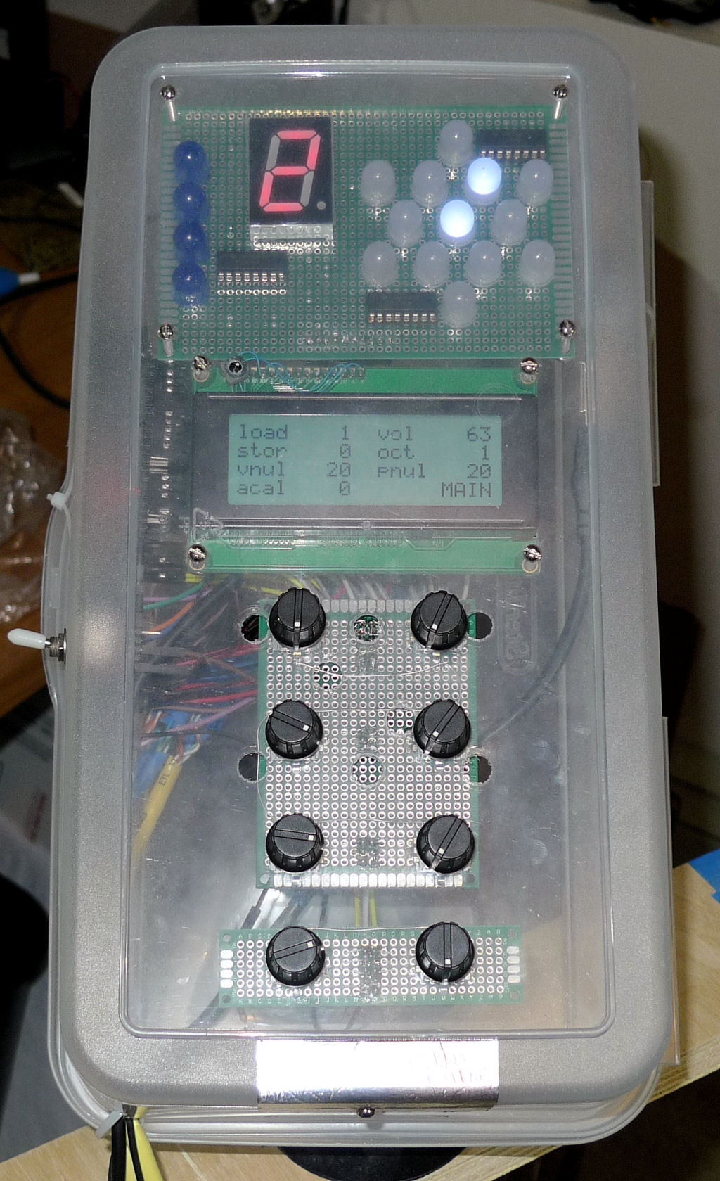
Encoder 7 (the 8th encoder) and the LCD position (lower right) that corresponds to it is the UI page selector.  You can see an older version of the UI it in action here (preset load and store was the main page back then): [LINK].  You can't see my hand, but I'm rotating encoder 7 to flip between UI pages.  The main page is the first page, and there's a hard stop at the first and last pages, so a simple counter clockwise quick twist of encoder 7 gets you back to the main page.  You won't need a button, but maybe you could use it for something else, like auto-calibration.  I used to use one of the encoder pushbuttons to do auto-cal, but twisting an encoder is much easier.

"4)  So for the front panel I'm planning on including the 8 encoders, LCD display, dimmer pot, power switch, maybe a couple mini jacks, and some future PP control holes. And the big green button, which is going on anyway just because I want it -I could just duplicate the encoder 8 push button function for now.

For the back there would be a phone jack audio output, maybe a duplicate or line level PP output, power adapter jack, and maybe panel mount USBs for the programmer and UART.  Any other suggestions?"

I'm powering via the UART USB cable.  If you want to power another way you'll need a ground somehow.  You might also put resistors on the UART leads to keep them from back-powering the FPGA if you power some other way.  My genuine Altera programmer also has idiotic / dangerous power cycle issues: if the programmer is powered down (USB disconnected) with the FPGA powered then the FPGA backpowers the programmer, which pulls a huge load and can damage things.  Your programmer is different and so may not have these issues. I don't think you'll use the programmer very often at all, so just having access to the programming header on the FPGA board should be sufficient.  I stuck my programmer inside for ease of development, but rarely use it at this point and will at some point remove it.

"5) If it works out that I can have the FPGA eval board plug onto a main board without cabling, do you have recommendations on any unused pins that should be brought out to accessible solder pads for future expansion, or any that I can be certain will not be used so that board space is not wasted?"

If it doesn't hurt to pull unused pins out to pads then I would do that.  If that's too painful, then pull out however many are easy for you.  Internal pin assignment is a quite flexible resource inside the FPGA.  There are a few pins that have more dedicated global resources, like the PLL clock inputs.  And the pins tend to be paired for LVDS if you want to use that (I'm not in this design).

Did you grab my FPGA pin spreadsheet? [LINK]?  It shows what pins and their types are brought out to the board headers.  No clock pins are on the headers, and I've avoided using pins 3, 7, 10, and 11 because they go to the 4 LEDs on the board (which could be desoldered to allow their use), and also avoided pin 125 which is the FPGA reset.  If it's not clear, the FPGA board provides +3.3V to the rest of the system via the header pins, and the 5V pins are inputs or outputs depending on how you're powering the board (outputs if you use an external adapter plugged into the barrel connector on the board, inputs otherwise).

"6)  Finally, I know you don't like to get pinned down on this, but I may want to have a little fun with the logo on my ugly prototype.  Is it dLev, dLEV, d-Lev or something else?  How about the "Wallin" (small print, upper left) "d____" (large print) "Digital Theremin" (medium print, under the name)?  Nothing will be set in stone, unless I make the housing using some of my leftover granite tiles..."

Ha ha!  Let's go with D-Lev (and maybe no "Wallin" - it's just not very sexy sounding).

Posted: 11/6/2018 12:31:09 AM
pitts8rh

From: Minnesota USA

Joined: 11/27/2015

So, while I'm quite excited to see where you might take the physical portion, I'm concerned that you won't get the full "experience" (for whatever that's worth) before changing things too much (I truly wish you could spend a month with my prototype)

I probably could have saved you some writing time if I had phrased that final question "Your technical thoughts on this?"  I was mainly asking if you had any thoughts about RFI/EMI or signal integrity issues. I have my own, but I wanted to hear yours.

But since you touched on other subjects, let me touch back.  On this next part we probably should just agree to disagree.  I not sure what I might not be able to experience by making the few changes that I have described.  I will be building to your schematics and general plans, complete with plate antennas, using your software, and virtually identical controls as a minimum.  The antennas will be on swivels and on arms of adjustable lengths.

But what I won't be doing is using plastic containers and Dupont jumper wiring, because I don't have to and I don't want to build it that way.  I think time is best spent putting forth some effort making a few incremental changes that put the design a step or two closer to something that I like and would possibly appeal to more traditional thereminists as well.  The antenna plates won't be in boxes because they don't need to be, and some things will be arranged differently physically. 

The only significant functional difference that I have talked about here recently is the separation of the tuner from the main console.  I play seated, ideally with the controls directly in front of me, and a short extension arm for volume and a long one for pitch.  I gaze (if my eyes are open at all) somewhere out in space in the direction of my hand.  A tuner on the console is going to be nothing but peripheral flashing lights.  And playing visually to a tuner anyway, regardless of whether placed conveniently or not, would in my opinion be a big step backward in the learning process at this point.  I like to have a fast waterfall tuner out there sometimes to check my pitch accuracy, and I do sincerely want to try your tuner as well.  But relying on visuals for real-time pitch feedback (except for training exercises) is something that will only get in the way.  I just have a feeling (no supporting data) that when it comes to playing accurately at speed, auditory feedback in the brain is a direct connection, while visual feedback may as well be coming in by email.

It is possible that you were thinking of earlier discussions where I asked about the viability of using traditional rod and loop elements.  I am cautious enough to know that if I end up going that route it is better to do it from the position of having a working prototype, with plates, as a starting point.  I have every intention of giving plates a fair test and I will spend some time with them to do that, but as you know I have legitimate concerns.  Those concerns come from observations of the way my hand intercepts the constant pitch "surfaces" that surround the pitch rod.  I have learned to work off those prolate-spheroid shapes both horizontally and vertically, and Electromagnetic Fields 101 tells me that the constant capacitance  constant pitch surface contours for plates are going to be significantly different.

Having configurable pitch linearity in software is a great thing.  But linearity is very much in the arm (and hand, and body, and stance) of the beholder, and I think that plates may have a different feel at close ranges.  If your pitch field is large enough that normal playing distances avoid flat plate distortions, that is good.  But then I start thinking about the effects of z-axis arm movements in the more spherical far-field (I mean distant field, not the antenna terminology)

I am excited to build your theremin and try it out.  And if I can't come to terms with plate antennas for the reason mentioned earlier, I will change them to something else and try that in an attempt to make it feel somewhat similar to other traditional theremins.  It's good to practice on different theremins and guitars, drive different cars, and fly different airplanes.  But I really don't want to have to significantly change a playing style to adapt to a particular theremin.  You say I won't have to, and that is good enough for me to go on to build it.  But don't worry about the changes that I am making detracting from the experience.  While I am completely at your mercy for the FPGA portion, when we get into the analog, I am entirely comfortable making changes, at least until theremins exceed 22.5GHz, which is where my comfort zone runs out. Many times when I ask you a question about this area, I already know the answer and what I plan to do, and I just legitimately want your opinion before doing it. 

But hey, let's get on with building it! Rant over.

I don't have plans at the moment to generate stereo, so yes there is a second channel available.  It would be a software change, the FPGA logic is already stereo.  And I bet we can do that processing in software to your satisfaction

Were you talking about doing the pitch preview in the FPGA?  That would be great, but here would be my wish list:

1) Dedicated full time encoders for at least functions 2) and 5) below, and maybe more.
2) Volume
3) Variable slope PP volume attenuation with pitch (I use about 40db/decade external fixed filtering on PP, not quite enough for me)
4) Variable slope (from positive to negative) PP volume with Theremin CV
5) Variable threshold intercept for item 4)
6) Some timbre control can help greatly with low pitch audibility. But if not, a sawtooth or low duty pulse train would be fine (no sine or odd harmonics only)
This sounds like a lot of work in FPGA world.  At least a fixed analog signal on one of the SPDIF channels would be fine for now.

I'm powering via the UART USB cable.

I can do that too.  What is your total current, approximately?

You must be logged in to post a reply. Please log in or register for a new account.