Let's Design and Build a (mostly) Digital Theremin!

Posted: 11/18/2018 2:39:26 PM
pitts8rh

From: Minnesota USA

Joined: 11/27/2015

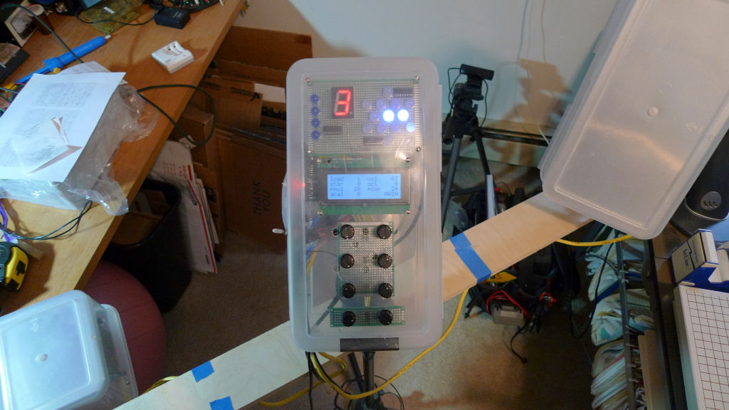
Also (color): Because I'm using different color LEDs I can't use a colored bezel in front of them to improve contrast, so was thinking of going with a smoked bezel, but that might hide the LED positions too much.  I believe one could go with a single color for everything and not hurt readability / recognition. A black PWB background for them would probably definitely raise contrast, something I intend to do on the next go-round.  Any thoughts on this?

Neutral density might be the best compromise, although since white LEDs are not monochromatic you might experiment and find some filter color that lets a muted red and blue through while allowing the brighter (filter color) pitch display.  A black pcb solder mask alone is still going to let the LEDs and the 7-segment background show through. 

Another quite easy thing to do is make your panel from clear acrylic or polycarbonate.  Mask off areas on the back side that you wish to remain clear, then paint the back side black (or even multi-color with additional masking).  When you remove the masking, you will have clear windows over the displays.  Now you can cut different color transparent film to glue or tape over the back side of the windows.  Voila - a nice shiny panel that is immune to paint scratching.  Even the worst sloppy paint job with sags and hairballs will look perfect from the front side through the clear plastic.  Some paints are not good for the health of the acrylic though.

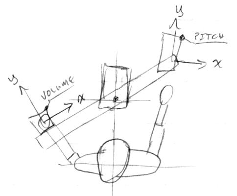
You rascal! :-)  Very interesting idea!  It puts more distance between the tuner and you, thus making it "smaller" but allows you to keep you eye on the pitch antenna.  If it weren't for interference I'd probably stick the tuner smack dab in the center of the pitch antenna, and this is one way to do it.  So you're going to do a mild parabola to make it appear bigger?

The opposite curvature, as in "TUNER IN MIRROR IS CLOSER THAN IT APPEARS".  I was thinking of a wider field of view, not narrower.  Of course you could go with the parabola and project a real image of the tuner right in front of your face, but I don't want to have to wear reading glasses to see it.

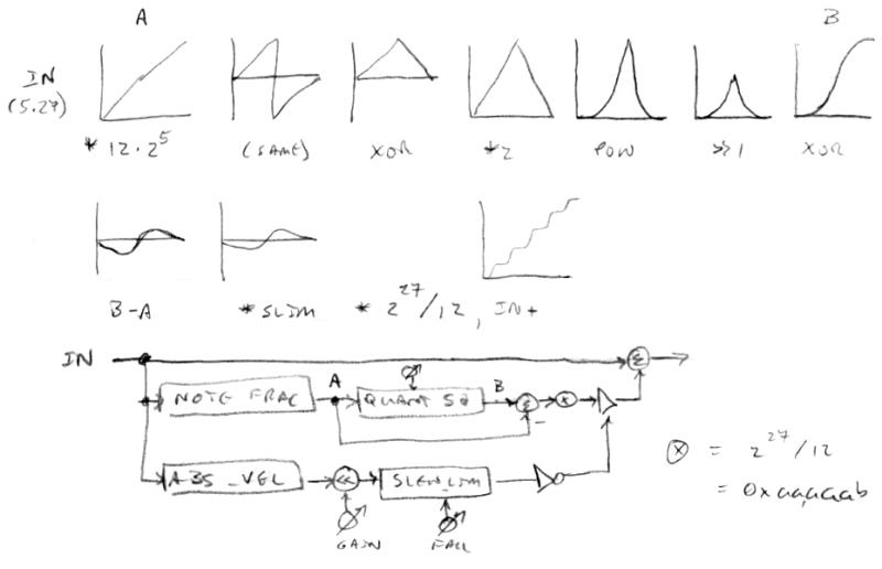
A parameter test and secondary 7-segment lookup table, ~20 lines of assembly.  Mode knob is already there (often the determining factor!).

If your HDL could correct the rightward slant built into the display modules, that would be impressive .  Actually a non-italic 7-segment made as part of a custom display panel would be simple to do.

Posted: 11/18/2018 3:55:42 PM
dewster

From: Northern NJ, USA

Joined: 2/17/2012

Sweet!!  Roger, I bow to your super human fabbing skills!

I posted this rough sketch a while back, and it turned out to be pretty much spot on in terms of where the prototype is now and how I address it when playing:

Here's a player's eye view of things, with the (~wide angle) camera placed where my head normally is for playing:

So, from both of these I hope it's fairly obvious that the pitch antenna is in clear view when staring at the tuner.  The distance from the center LED to the center of the pitch plate is ~300mm (as the crow flies).

You can (and absolutely should!) do what you think best in terms of physical design, I just don't want anyone thinking I didn't put a certain amount of thought into the ergonomics of the prototype.  I figure players can easily rack up thousands of hours on an instrument, so why not make that experience as user friendly as possible.  I still think the knobs should be grouped together below the LCD, but I play with reverse volume sense, and so have to "man" the volume antenna with my left hand to get any sound while knob fiddling with my right hand.  Normal volume sense would often leave both hands free.

The next pitch antenna will probably have the ball mount on the bottom of the box rather than the back in order to move the plate back a bit from the player.

============

Also, thank you again for your pitch correction observations, I'm mulling them over.  I'm not completely happy about how "magnetically note-centric" my approach is, and using dP/dt to scale back the pull might be the best approach as it is blind to note divisions.  I believe it would entail highpass filtering before note division, rather than lowpass filtering after note division.  The quantization function could perhaps have a softening control, though I had this in the past and didn't find it useful.

Right now I'm in the middle of reviewing the velocity mechanism for what feels like the 100th time, trying to make it automatically scale with knee location.

Posted: 11/19/2018 6:56:25 PM
dewster

From: Northern NJ, USA

Joined: 2/17/2012

Knee / Velocity / Attack / Decay (maximally polished version)

Everyone's pretty tired of this one by now (imagine how I feel!).  But I just finished some work on the volume side post-processing and wanted to yak about it a bit.  Here's the latest (and hopefully final) data path:

Same old stuff except for:
1. Reversed level is used to "gain-down" the velocity (via offset) for lower level settings, which makes the velocity strength consistent over the level range (the level and velocity knobs were heavily interacting).
2. Velocity strength is now set via the knee knob (the knee and velocity knobs were more or less tracking together and so have been combined).

This forms pretty much exactly what I was looking for when I started down this loooong path.  Depending on the knee knob setting it gives:

1. no knee
2. soft knee
3. hard knee
4. hard knee + a bit of velocity
5. hard knee + wide range controllable velocity
6. hard knee + maxed out velocity
7. hard knee + maxed out velocity with easy retriggering inside the knee.

All with a linear and entirely playable zone inside the knee (except for #7 obviously).  And by twiddling the rise and fall knobs you can get percussive envelopes, reverse envelopes, etc.  Consumes a mere 4 knobs.

As I've whinged on about previously, if you're doing it right you'll end up spending more time fiddling with parameter inclusion/removal & scaling than the actual data path those parameters control.  It's amazingly time consuming.  Adding a single subtraction here took me like two days.

Posted: 11/20/2018 8:45:52 PM
dewster

From: Northern NJ, USA

Joined: 2/17/2012

Is That All There Is? 

Bringing some of my presets back to life now that the D-Lev has 12 state variable formants instead of 6.  For cello I'm starting at 196Hz and going up from there 3.5 semitones at a time (196, 240, 292,... , 1205, 1479, 1815) with all amplitudes and Q the same.  To fill in the top end I've got the inharmonic resonator high pass filter set to 773Hz, and the rest of its settings dialed in by feeding noise into the whole thing, watching the spectra, and making the intersection smooth and the inharmonic resonance spacing similar to the 12 state variable formants at the intersection (this is linear spacing vs. exponential for the SVF's).  To my ears, SVF formants sound better - smoother, less artifacty - than the inharmonic resonator formants, so the voice has improved somewhat because the inharmonic resonator is doing less fill in work.  See what you think: [MP3].

I've read string synthesis tutorials on-line that say you need a formant every semitone! And analog string filters have like 40.  I've only got 12 with some filler, I'm not doing any amplitude shaping at all, and it sounds pretty OK to me.  Do my ears need calibrating, or am I missing something?  Why does something as complex as a cello or violin boil down to an exponentially spaced resonance bank?  Roughly (or, equally strange, precisely) dial up a handful or two of resonances and a cello pops out.  It just seems too easy.

So, having at least 12 formants seems worth it, and you'll probably want a lot more if you don't have something like the inharmonic resonator in there, puttying over the gap.

Posted: 11/20/2018 9:51:50 PM
tinkeringdude

From: Germany

Joined: 8/30/2014

Those great numbers of formants... maybe those people are referring to string ensemble sounds, not a single instrument?
*wildly guessing*
And the current sample does sound nice, I don't think your next ear doctor visit is very urgent

Posted: 11/21/2018 1:08:20 AM
dewster

From: Northern NJ, USA

Joined: 2/17/2012

"Those great numbers of formants... maybe those people are referring to string ensemble sounds, not a single instrument?"  - tinkeringdude

It could be I suppose.  I've probably pointed to it before, but this article talks about synthesizing cello resonances with a Nord: [LINK]

He starts at the lowest resonance of a contrabass, which is 58Hz, does one per semitone up to 880Hz, then stretches the rest to just below 20kHz, using 48 total (due to limitations of the Nord I believe).  He says 48 aren't enough, and feels the need to adjusts the individual amplitudes per note via interpolated tables in order to get closer.  But there isn't any "based on a real cello" resonance location going on, other than the lowest resonance, with the rest fleshing out the space.

I could maybe do 48 but I wouldn't have much left over to do anything else.

Posted: 11/25/2018 6:19:29 PM
dewster

From: Northern NJ, USA

Joined: 2/17/2012

Further Adventures In Pitch Correction

Roger (pitts8rh) has spurred me on to consider a more professional level of pitch correction (thanks Roger!).  As I said before, my current pitch corrector works well but is a bit too "note centric" in that off-center vibrato which bleeds over into the neighboring note can drag the correction off center.  And it often corrects "too well" in that it voices recorded together beat against each other.  I very much like the "one knob" aspect of it, and like that the adjustment of that knob goes from off/unnoticeable, to a range of noticeable, to full quantization (I think all knobs should do something really obvious and non-redundant/overlapping).

The gist of pitch correction is this: generate a correction / error function and apply it to the pitch number.  The function is obviously the same/repeats for all notes.  The simplest function I've found is to use the linear note ramp (a straight line going from one note to the next) "layed down" on the x axis to form a sawtooth as the error, and subtract this from the pitch number.  Low pass filtering the error slew limits the abrupt changes between notes, knocks the sharp edges off, and lowers the amplitude (strength of correction) for faster changes, and adjusting the low pass corner frequency markedly changes the correction experience.  Reducing the error amplitude with an explicit fractional multiplication by, say 0.9, would actually fix the odd sounding unison "too perfect" correction.

If we want more control we could use line segments to construct the correcting waveform, but line segments are kind of hard to do without division, and division is hard to do without floats, and line segments aren't smooth anyway.  A good candidate here is the type of squaring based smooth quantization I'm doing for the LED tuner brightness (I was also using this to generate glottal waves for a while).


The above is an Excel plot of the correction function generated via various logical transformations and repeated squarings (here 3, or raised to the power 8) of the note ramp.  The lighter trace is the correction function multiplied by 0.9, and the darker trace is this added to the pitch number to produce the corrected pitch number from note 0 to note 1.  Note that there's a broad plateau at each note center, the correction isn't "perfect" due to the 0.9 multiplication, and the transition between notes is fairly steep but smooth.

If we apply the above directly we get smooth quantization (yes, an oxymoron), not pitch correction.  Pitch correction requires amplitude modulation of the correction function.


I got the above up and running on the D-Lev prototype the other night and have had a couple of opportunities to play around with it.  The upper graphs show the transformations applied to the note ramp to get the correction function.  Modulo multiplication to get the note fraction, XOR via full-width MSb to fold the upper half down, *2 to get full scale, repeated squaring, then backed out doing inverse functions, laid down on the x axis via subtraction of the note fraction ramp, followed by note scaling, amplitude modulation, and mixing with the pitch number.

At bottom is the signal flow with three paths.  Top path is the mix, middle path generates the correction function, bottom path modulates the correction function.  In the ABS_VEL block the absolute instantaneous velocity is found via subtraction of the previous pitch number sampled at 48kHz (differentiation), then 4th order low pass filtered at 15Hz to reduce noise.  Bulk gain is applied via left shift.  The result is slew limited in the fall direction only, giving a leaky peak hold.  Finally a negation of all bits reverses the direction.

The setup of this arrangement is much more subtle than my previous one knobber - in fact, I finally broke down and made a debug parameter type that displays 8 digit hex on the LCD in order to get some observability of the modulation path inner workings.  Not too surprisingly, the quantization squaring knob has the most noticeable influence, with 3 squarings around the most you might want in terms of slope between slowly played notes (if not going for a quantization effect).  The gain knob functions more as threshold for how much hand movement is required to scale the correction back.  The slew limit knob seems the least useful, and could perhaps be replaced with a constant.  I need to try the LOG2 trick to gain up and reduce the dynamic range of the velocity, as this worked like a champ on the volume side envelope generation.

Overall, I like this better as it totally gets out of the way of vibrato, and the note-to-note transitions are less magnetic.  However, there's clearly a tension between too much disengaging and too little (gain knob).

Posted: 11/26/2018 4:29:32 PM
pitts8rh

From: Minnesota USA

Joined: 11/27/2015

We could more closely study the behavior of the pitch correction in my Voicelive processor if it would help with your development.  It would be a good idea to confirm that the assumptions that I made back then (and just fed to you as fact) are correct.   I now have some equipment that I don't think I had back when I was experimenting with it on the theremin.  I'm thinking of some tests looking at exactly how the three parameter settings affect the pitch correction when applying slow sweeps to notes and variable vibrato magnitudes & rates around the notes, using an arb generator as an input source.

I don't think the Voicelive is any ultimate pitch corrector, but they did do some smart things that make you think a little harder about what might be really needed for the full gamut of pitch assistance from Kiddie Thereminie to a completely non-intrusive stabilizer that even the best players might want to use. 

I have ideas on some tests to do, but if you have any requests post them or contact me in case I get some spare time around the holidays.  I don't think I'll be able to do much close-up board work anyway starting next week and running at least into January.

Roger

Posted: 11/26/2018 11:08:50 PM
dewster

From: Northern NJ, USA

Joined: 2/17/2012

Hi Roger,

I'd be most interested in the results of any testing you feel like doing!  I'd try the things you've listed, variable rate ramps across several notes, variable rate ramps from one note to the next, variable speed and width vibrato both centered and off-center.  Perhaps with the goal of proving your mental model of how it works, rather than a quantitative analysis, as there are so many variables and so many tests (geometric explosion)?

The thing I'm contemplating at the moment is dealing with the midpoint region between notes.  If I move my hand really slowly it exposes the steepness of the note transition.  My playing style is kinda sloppy, so it benefits from a wider "correction plateau", but the wider the "correction plateau" is the narrower and steeper the transition region is.  Though with a milder correction curve of two squarings (^4) or three squarings (^8) the transition isn't very obvious.  It may be that I'm just overly used to having to really dial back the low pass filtered 100% quantization curve of my previous pitch corrector?

I tried LOG2 velocity gain / compression yesterday and I think it's directionally incorrect.  I've got velocity squaring in there now, which interestingly does triple duty as gain / expansion / absolute value.  I also removed the 4th order LPF without obvious deleterious effect.  The slew limiter is more important than I initially thought, and am thinking that something like a 10:1 rise/fall rate (rise rate 10x faster than the fall rate) might work well, though the instant rise is currently working fine AFAICT.  Without the modulation value being displayed as hex on the LCD I'd be pretty much in the dark, so it's especially important to properly scale and limit the parameters to useful ranges, and perhaps combine some to further exclude uninteresting combinations of settings.

Posted: 11/27/2018 9:24:34 AM
pitts8rh

From: Minnesota USA

Joined: 11/27/2015

Two quick questions:

1) What's on the other end of each of the pb_i[x] connections shown below?

2) What do the BANK B1, B2, etc. divisions mean?  I've ignored them for routing so far.  I'm wondering if they are just some groupings on the FPGA chip itself. 

You must be logged in to post a reply. Please log in or register for a new account.