Let's Design and Build a (mostly) Digital Theremin!

Posted: 2/15/2019 11:18:34 PM
dewster

From: Northern NJ, USA

Joined: 2/17/2012

12Hz LCD Update FFT Bump: Bumped Off

I just finished an assembly code edit that killed the LCD update 12Hz bump in the axis FFT.  I decided to go with option #3 above, where the parameters and screen values are only updated when an encoder or pushbutton changes.  This also killed my pitch correction velocity display, so I've got to either make a work-around or do something else.  I'm leaning towards co-opting the volume axis display when velocity view is enabled via an encoder setting.

Posted: 2/16/2019 9:21:12 PM
dewster

From: Northern NJ, USA

Joined: 2/17/2012

Oscillator FFT Bump: Bumped Off

An idea I had years ago: use the pitch number to dynamically set the cutoff frequency of an upstream low pass filter which is filtering the pitch number.  This would naturally apply more filtering to the more noisy far field.

I implemented it today in assembly and it's working amazingly well on my D-Lev prototype.  It uses the pitch number before pitch correction just to keep steps out the feedback loop, but I'm not sure that's actually necessary.  I thought I'd maybe have to pre-filter the pitch number going to the filter cutoff control, but that doesn't seem necessary either.  So it boils down to almost nothing.

To kill the "traveling hump" in the pitch and volume axis numbers, I've got it set up so the filter is positioned one octave below the pitch number, which gives -24dB attenuation for the 4th order low pass filter at the "hump".  There's a hard limit of 16Hz on the low end (8Hz seems to work well too, but that scares me), and the maximum top end is currently variable (controlled by a knob).

A bit of finessing: the -1 octave filter offset follows negative settings of the oscillator octave switch but not positive settings.  This gives extra filtering when playing high pitches in the far field.

It was a snap to implement, should have tried this a long time ago.  It co-opts the hum filter low pass section to do double duty so it's quite efficient in terms of real-time.  It currently only dynamically filters the pitch axis number, not the volume axis number.  I think players are likely more sensitive to bandwidth variation on the volume axis so I'm holding off on that.  If I were to dynamically filter the volume side it would likely be a notch filter rather than low pass.

The noise is so low now that quantized steps are clearly visible at very low oscillator pitches - noise was dithering them before.

===============

For the past week or so I've had a software diagnostic load in the D-Lev that sends the pitch operating point to one side of the audio for analysis, and thus also to my headphones.  During my testing I've noticed very clear indications of AM stations being "tuned in" - nothing I can hear as demodulated voice, but beating that must be RF.  Sometimes at night the pitch axis jumps around, but never during the day, which is also an indication of AM interference.  As a result of this I'm going to stick the pitch axis above the AM band with a 0.5mH tank coil.  I've already briefly experimented with a 0.5mH connected to the AFE2, so I know it should oscillate OK.  I may also try a more "cubic" antenna plate enclosure for the pitch side, much like I currently have on the volume side.

Posted: 2/18/2019 6:56:28 PM
dewster

From: Northern NJ, USA

Joined: 2/17/2012

Pitch Axis AFE2 & 0.5mH Coil

Not to be outdone by Roger's magnificent handwork, I proudly present my current pitch side:


AFE2 in the back mounted with screws on chopped ballpoint pen body standoffs; 0.5mH coil I had sitting around mounted solidly and permanently (!) on top of the old 4mH coil PVC knockout with a piece of painter's masking tape.

Repumped the FPGA and it's oscillating at 1.844MHz.  I'm seeing 3.36Vp-p at the C divider (1pF/150pF) so the swing looks healthy with 

  3.36V * (151pF / 1pF) = 500Vp-p 

voltage swing at the antenna (the swing is actually somewhat larger than this due to scope probe C loading).  Stability at 50ms trigger delay looks solid.  The pitch side seems a little less noisy, and that was the impression I got when I first tested the AFE2 / 0.5mH on the bench too.  I'm still seeing some far field bobble associated with the audio signal, particularly when the octave switch is set to negative values.  I may have to set that filter to 2 octaves below the audio pitch and allow it to go lower.

I tried the new FPGA load before I changed the coil and it was oscillating at 2x the LC resonance (~1.2MHz) which is weird.  So I guess the FPGA load has to be somewhat tailored to the coil values (it has to be anyway to keep the desired low pass response of the DPLL in the ballpark).  If I ever see this behavior in the future I'll put a programmable upper hardware limit on the DPLL lock range (it had both upper and lower limits at one point, but they were never used them so I took them out).

The beauty part of butt-ugly prototypes: You get pretty fearless when it comes to trying things out that will make them even butt-uglier (drilling new holes, taping things down, etc.).  But an obvious problem with this is they're so butt-ugly only a mother can love them and see their inner beauty.

Posted: 2/19/2019 3:55:09 PM
dewster

From: Northern NJ, USA

Joined: 2/17/2012

2019-02-19

Some combo work applied to the tracking filter and pitch correction code:


I was worried that noise post axis processing modulating the LP4 tracking filter cutoff frequency might be introducing amplitude modulation, and I definitely saw noise turning off the pitch corrector mid-field via its velocity feature, so I added a 2nd order lowpass filter set to 16Hz and am using this to feed the tracking filter cutoff control and pitch corrector velocity.  For the tracking filter, the octave switch is rectified to give only 0 and negative results, this is offset by -2, which shifts the output of LP2 to the right (negative shift left), causing an octave shift of at least -2.  This is limited to 8Hz min and variable max, and then fed to the tracking filter.  Noise levels as witnessed on the LED tuner and via diagnostic software loads have been dramatically lowered by this arrangement.  Almost out of real-time on the pitch axis thread.

All I'm playing lately is The Godfather Theme on violin [MP3].  Hardware / software development provides ample opportunity for practice (when the thing is actually up and functioning OK).

[EDIT] I forgot to include an EXP2 function right after the LP2 pre-filter on the pitch tracking side. 

[EDIT2] And of course the LP2 filter is acting up on the pitch tracking side, so just I moved it into the pitch corrector.  The pitch tracking filter now has no pre-filtering.

Posted: 2/20/2019 10:41:02 PM
dewster

From: Northern NJ, USA

Joined: 2/17/2012

(Sort of) OT - Neural Nets

Ran across this absolutely fascinating 2015 github post via Hacker News:

http://karpathy.github.io/2015/05/21/rnn-effectiveness/

Train a recurrent neural network overnight and in the morning it will: write almost executable code, complete with comments!  Learn English words, grammar, and syntax well enough to create almost believable research papers on mathematics!  

These things utterly flabbergast me.

[EDIT] - I say "sort of OT" because neural nets can speak and do other synthesis tasks amazingly well by just predicting the next PCM sample!

Posted: 2/23/2019 6:18:08 PM
dewster

From: Northern NJ, USA

Joined: 2/17/2012

Antenna Homologation

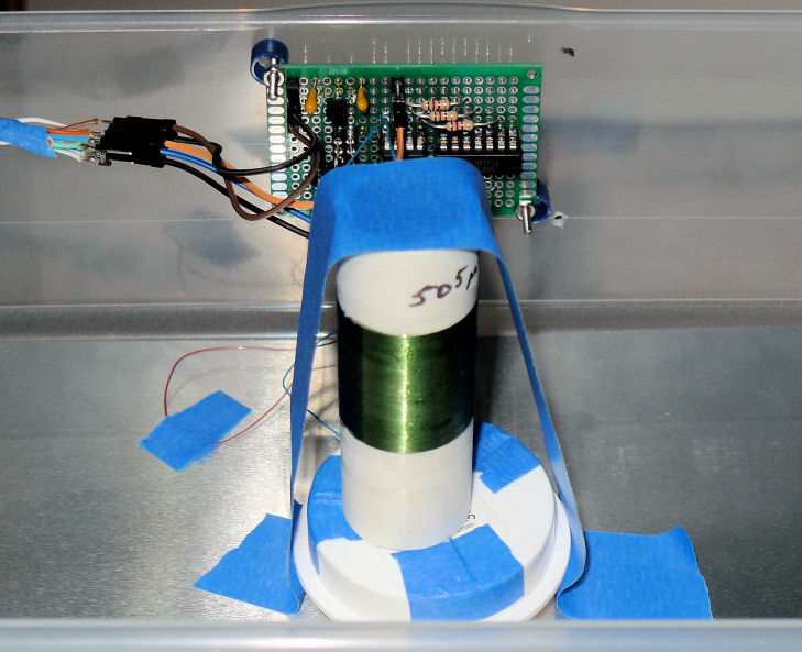
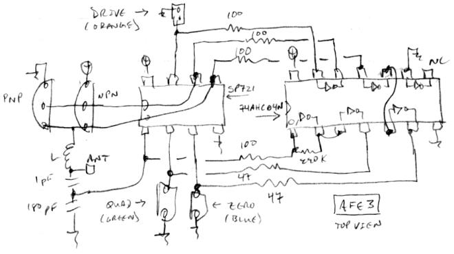
Bought another small "Holds CDs!" Sterilite plastic box (model 1803, UPC 073149803863) from Home Despot the other day (same box I'm using for the volume antenna).  Cut some 150mm wide aluminum flashing to 300mm long, bent/mangled it on a small dowel, and stuck it inside.  Moved the AFE2 and 0.5mH coil from my pitch antenna over to it, and mounted it on a 1" RAM rubber ball mount I bought a while back.  Here's what it looks like:


New pitch antenna box, viewed from the playing position.  It's a somewhat smaller target.


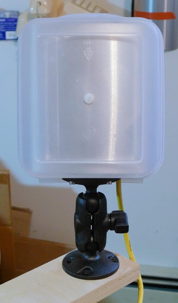
View through the back, with the antenna top oriented to the left here.


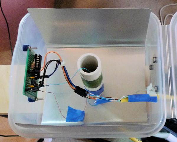
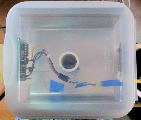
View with the back open.  Coil in the center, AFE2 board to the left (top when playing).  For a production type build I'd probably try to locate the AFE2 on the right (bottom when playing).  The cable strain relief isn't ideal here (cable clamp zip-tied to a screw).  The coil is only held in place by sitting over the plastic mounting screw, with the back of the box (when closed) holding it tight to the plate.  Not ready for prime time!

The new antenna popped right up when I switched the D-Lev on, which is a great thing about using a digital phase locked loop for the oscillator.  No hunching over tuning slugs for hours, putting the cover on, taking it off, etc. it just works.

It resonates at 1.763MHz (my old pitch antenna resonated at 1.844MHz).  I had to adjust the linearity control to -4 (this was +3 for the old pitch antenna). It's interesting (and really great!) that the simple linearization algorithm that I discovered is able to largely correct antennas with such a different geometries (the old antenna was a flat plate).  The linearity algorithm seems robust and quite not-critical, with the only adjustment a minor influencing of the near field.  You almost don't need the adjustment knob (but it's nice to be able to tweak it).

I'll play this for a while to see how a smaller pitch target feels.  Hopefully it will be OK, and I'll be able to employ the same box for both volume and pitch, just with different coils inside.  Been meaning to try this for a while now, good to finally address it.

=================

3D Antenna Geometry

From my simulations - and now real-life experience - with plate antennas, it's clear that they don't have to be flat plates in order to be linearizable.  As long as most of the antenna can "talk to the hand" in the near field, then the cross section can be a U, a square or round tube, a pie plate, etc. making the whole thing more compact.  Compactness isn't the ultimate goal, however, if it reduces the playing "sweet spot" to something difficult for the player to stay aligned to.

I imagine a 3D plate antenna could entirely enclose the coil and AFE, and thus provide some electrostatic shielding for the internals.

Posted: 3/3/2019 7:03:45 PM
dewster

From: Northern NJ, USA

Joined: 2/17/2012

Even-All-Odd Oscillator

Whew, been down for the count for the last week or so volunteering, but that's mostly in the rearview mirror now, so I've had some time to work on something Roger's been urging me to do, to wit: add variable even harmonics to the audio oscillator.  The oscillator already had variable and axis modulatable odd harmonics, but I really couldn't understand how to do even harmonics, as the extreme case of all even harmonics doesn't include the fundamental (which is odd) and indeed would just be the case of all harmonics moved up an octave.  But intermediate mixing will still have the fundamental, though it would be somewhat suppressed depending on the mix level.

Another thing Roger helped me to understand is that the harmonic mixing/crossfading can be done with output waveforms.  I was doing the mixing at the phase modulation signal level, which is more complex and fraught with amplitude and modulation strength issues.  So the new oscillator is actually simpler.  I was also able to do the odd/even oscillator with a single SIN2 calculation: squaring the output of this gives a raised sine at double the frequency, which is required both for self phase modulation and for the even harmonic mix.

As usual, I first did a spreadsheet for proof of concept, to confirm all of the math details, and to calibrate the polynomial: [LINK]

Upper left is the base unit that scales the phase increment (frequency) input, accumulates it, and performs the polynomial scaling to keep modulation and harmonic content roughly constant with frequency, thus taming aliasing.  Upper right is the all harmonics unit that is driven by the base unit.  The SIN2 output is averaged to put a notch at Nyquist, and fed back as phase modulation.  Lower right is the odd / even harmonics unit that is driven by the same base unit.  Largely the same as the all unit, but the SIN2 output is squared to double the frequency (both output edges need to be "sped up"), then offset and scaled to give the even output.  Lower left is the crossfade unit, it switches between odd and even sources based on the sign of the mix control (negative=even, positive=odd), and uses the mix value to crossfade between this selection and the all harmonics source.

If you think about it, the crossfade from even to all to odd forms a continuum of sorts, from odd harmonics being suppressed to odd harmonics being accentuated.

It's simpler and cleaner than the old oscillator, and I think the harmonic blending is better.  I played around with the harmonic strength function but ended up just going with linear control here.  Linear control for the crossfade also seems to work well.  I also removed the negative region from the "harm" control as it seemed kind of pointless.

Except for an inversion, the recorded waveforms and spectra look just like the spreadsheet.  Looking back, I don't know why I didn't think to try this method in the first place.  It's quite clean and efficient.  Thanks again to Roger for his very gentle prodding and inspiration!

[EDIT] Here's a quick sweep of the oscillator with the volume and pitch axis modulations set pretty crazy (caution: LOUD!): [MP3]

Posted: 3/6/2019 5:28:23 PM
dewster

From: Northern NJ, USA

Joined: 2/17/2012

Organic = Analog + Digital + Compression

Our nervous systems are a blend of analog and digital.  Nerves communicate with each other by "firing" pulses of electricity.  These pulses are more or less fixed height and width, and thus digital.  Nerves sum and integrate incoming pulses over time and fire their own output when an analog threshold is reached.  So nerves internally are analog, and externally digital.

The retinas of our eyes are actually extensions of our brain, separated by nerve cabling.  There's a firehose of information falling on our retinas, and to make the cabling tractable, a fair amount of pre-processing compression must be performed at the retina itself.  Many optical illusions work by revealing the limitations of this compression scheme, the disorienting artifacts of which we are normally literally blind to.

The ear is somewhat similar, where nerve hairs in the cochlea detect (standing?) waves in the fluid, with distance down the cochlea equating to frequency, another form of pre-processing compression before the information is sent to the brain.  MP3 compression exploits gaps in our hearing sense that we are literally deaf to.

The brain itself oscillates with a somewhat variable low frequency bulk waveform.  I tend to think of brainwaves as both a clock and a dither source - providing global synchronization, and perhaps increasing the resolution of the processes.

The reason digitization of music and video works so well is due to temporal limitations of the analog and digital processes that form our senses - one only needs to make the sampling rate high enough to sufficiently oversample our senses.  And the reason compression of music and video works so well is due to the limitations of the compression systems our own senses employ.

Some claim digitization has a "coldness" and compression "degrades the sound" - and if not done well there certainly can be issues.  But our own highly developed "organic" senses rely heavily on both.

Posted: 3/8/2019 8:18:40 PM
dewster

From: Northern NJ, USA

Joined: 2/17/2012

AFE2 : A Dud

Here and there I'm seeing the new AFE2 (Analog Front-End, Version 2) lock onto lower harmonics, which is no good, I never saw AFE1 do this.  Yesterday I added a lower (-2 octaves from max) limit to the phase error accumulator but that didn't fix it as the harmonic lock point is above that (and a hard lower limit is kind of a kludge).  The problem seems to be a lack of snappiness in the squaring up of the C (capacitive) divider signal (1 stage instead of 2), and the sending of a >2x BW (bandwidth) signal back to the FPGA board.  I lowered the series resistor going back to 33 ohms which improved signal integrity, but didn't improve the harmonic locking.  So I'm afraid I'm at the point of giving up on AFE2.  At least there's a known good fall-back position.

Locking onto sub harmonics is a well-known thing that XOR phase detectors are susceptible to, but a while back I discovered it was ameliorated by a quirk in the way the transistor tank buffer behaves:

http://www.thereminworld.com/forums/T/28554?post=210884#210884

For AFE2, when the LC_DPLL is locked the return signal needs 2x the BW of the feed signal.  But when it's unlocked it requires considerably more BW in order to resolve small pulses and such.  And off-resonance, where the C divider amplitude is quite low, the pulses themselves aren't very well-formed as there is only a single stage of gain to square the tank signal up.  So the LC_DPLL has a pretty trashy signal - that has to travel through a cable - to work with when off-resonance.  For AFE1 the return BWs are pretty much the same as the drive regardless of lock, and there are two stages of gain squaring up the C divider.  I believe AFE1 is more or less the key to getting the volume axis LC resonance positioned above the pitch axis (and so have both out of the AM band) because of its relaxed BW requirements.

I'm going to try to modify my AFE2 boards to be AFE1's.  I'm thinking of lowering the return impedances on AFE1 to 47 ohms or lower, and maybe some or all of the others resistors as well.

Ah, well, it seemed like a good idea at the time.  C'est la vie.

Posted: 3/9/2019 5:42:05 PM
dewster

From: Northern NJ, USA

Joined: 2/17/2012

AFE3

Yesterday I spent a couple of hours converting the pitch axis AFE2 to the new AFE3.  Here's the schemo and rough layout that I followed when doing the rewire job:


It's actually a blend of AFE1 and AFE2 because the zero signal is driven post transistor tank buffer (ala AFE2) rather than before (ala AFE1).  I want both outputs to see the same delays as much as possible, to hopefully keep drift to a minimum.  I reduced the zero and quad drive resistors going back, though that probably wasn't all that necessary as the signals look really good and quite snappy back at the control console.  The FPGA drive signal might need a little more programmable oomph as it looks a shade anemic.


You can see that I went kinda crazy with the ESD protection, as every SP721 pin is now utilized.

I tried a variety of things but couldn't get it to lock onto sub-harmonics, which is great.  Grasping the bare plate with my hand I got it to search for lock but it quickly found it again - that's neither surprising nor worrisome behavior, and anyway can't even happen with a moderately insulated antenna.

This is also my first experience with the 74AHC04N and it is quite positive.  The VT (threshold voltage) is amazingly close to VCC/2, which allows maximum dynamic range at the capacitive divider.  Exactly what you want when biasing CMOS into its linear region.

I'll convert the volume axis AFE2 => AFE3 soon.  Today I want to work on the SPDIF TX code as it often fails timing closure during the FPGA compile.  I'll throw a bunch of flip-flops at it to improve the timing margins.

You must be logged in to post a reply. Please log in or register for a new account.