Let's Design and Build a (mostly) Digital Theremin!

Posted: 6/20/2019 10:49:32 PM
dewster

From: Northern NJ, USA

Joined: 2/17/2012

Continuum Type Initial Pitch Correction

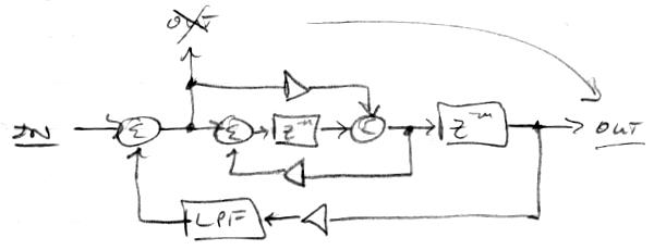
Yesterday something made me think of the Haken Continuum, which got me to thinking about what I imagine is the initial pitch method on it.  With a continuous controller like the Continuum, Theremin, violin, trombone, etc, the player 99.9% of the time desires that a given note start its life sounding on-pitch, rather than off-pitch.  The Continuum has the advantage here of real attack type actions happening on the playing surface to guide the pitch algorithms, whereas the Theremin generally doesn't.  On the D-Lev, however, one can fairly simply arrange things in SW so that when the volume drops below audibility the pitch correction becomes more aggressive.  I implemented this today and the results are quite encouraging.  Here is a view of the entire current pitch correction datapath:

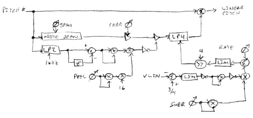
The section to the upper left is unchanged from before: There are three paths for the linear pitch number, the top path is the unmodified pitch number, the middle path expands each note to full scale and selects a portion of it to correct (span knob) with a certain strength (corr knob), the bottom path is 2nd order low-pass filtered (16Hz), and it then modulates the middle path with pitch hand velocity squared and a given variable influence (pvel knob).  The final middle path is 4th order low-pass filtered and combined with the top path as a feed-forward error correction signal.

The section to the lower right is new: The linear volume number is subtracted from 3/4, which establishes the threshold of audibility as -48dB, the result is limited, inverted, squared, and inverted, which gives a "hump" like shape below the -48dB point.  The strength of this is controlled via a squared parameter (subr knob), then combined with another parameter (rate knob), limited, and scaled by 1/16 to control the cutoff frequency of the 4th order low-pass filter.  This raises the filter frequency between notes, which lowers the settling time of the applied correction (the whole point).

I thought of modulating the pitch velocity with this scheme as well, which would make the correction below audibility more aggressive in the presence of high velocity strength settings (high pvel), but after playing with it for a while that seems unnecessary.  You can easily see it working if the tuner is set to post pitch correction, and you can easily hear it working if the pitch preview is enabled and set to "wheedle" when the playing voice is below audibility.  Otherwise, it's impossible to tell that anything is going on - other than that you are suddenly a somewhat better player!  Provided of course that your pitch hand is actually indicating the correct note "regions" at the time of their play.  These pitch quantization schemes do have downsides, and one of them is that they can make certain kinds of mistakes worse.  But, hey, don't set the knobs too crazy.  And (I assume) Continuum players have to contend with this sort of thing too (really sloppy playing + overly aggressive correction = big boo-boos).

[EDIT] Here's a sample where it's turned all the way up and you can hear the pitch preview stepping between notes, but the notes themselves smoothly gliss: [MP3].  It does seem to improve my playing.  I have no idea if this would be useful / too aggravating for those who rely on pitch preview, though it can be turned down to be less "steppy" sounding yet still lend accuracy to the initial phase of notes.

Posted: 6/29/2019 3:50:23 PM
dewster

From: Northern NJ, USA

Joined: 2/17/2012

Axis Decimation Inventory

Buggins got me to thinking about how the D-Lev pitch and volume axis operating points (frequency numbers) are decimated (down-sampled) for use by the software. Down-sampling is something I've struggled to understand sufficiently to feel confident that I'm correctly implementing it in this project.  If anything, my approach is probably overkill, and so hopefully blameless.  Here is the pitch side (volume side is the same, but cutoff points and such can vary depending on the inductor value and the desired final bandwidth):

1. On the left the DPLL is operating at 196.666667 MHz, which is 4096 the audio sample rate of 48.014 kHz.  (I couldn't do exactly 48 kHz due to the limitations of the FPGA clock dividing / multiplying / conditioning PLLs, and there are only 2 in the target FPGA.)  The DPLL acts as a low-pass filter for phase noise, and the cutoff here is set to 182 Hz (via FPGA code build parameters, with steps which are powers of 2).  A first-order roll-off gives 6dB per octave / 20dB per decade, which translates to -108dB @ 50 MHz.  108dB / 6dB/bit = 18 bits, of which perhaps 1/2 of this, or 9 bits are a real resolution increase due to filtering.  Due to the XOR phase detector, and due to the fact that the LC resonance is 1.4 MHz, there is a ~42 count (p-p amplitude) 2.8 MHz frequency triangle wave riding on top of the DC signal.  Since triangle harmonics go as 1/(n^2), the harmonic around 50 MHz is n=21, so the amplitude is down 1/21^2 or 1/441, which is down ~12 bits, or smaller than the triangle amplitude, so it doesn't seem like much of an alias problem.

2. Nevertheless, 26 bits of frequency are taken from the DPLL and fed to a new "pre" filter, which is a first-order low-pass set to 497 kHz.  This gives -39dB @ 50 MHz, which pretty much kills the XOR triangle harmonic energy.  The filter time constant (as are all of the filters here) is accomplished by right shifting, and here we're shifting by 32 - 26 = 6, which is a multiplication by 2^-6.  This gives a 32 bit output with no internal truncation.

3. The output of the "pre" filter is sampled at 1/2 the rate, or 98.333333 MHz.  Here we are concerned about energy above 1/2 this rate aliasing down, hence all of the "50 MHz" calculations above.  The sampling is done by enabling the following filter every other clock. 

4. A fourth-order low-pass filter set to 415 Hz follows, which gives -114 dB @ 24 kHz (where 24 kHz is, again, 1/2 the sample rate of the following stage).  This is a string of first-order filters, with internal width of the I/O + the attenuation factor (32 + 15 = 47) so as to keep truncation noise to a minimum.  To even out FPGA power demands, the pitch and volume axis filter enables are alternated here (this is a big filter taking slugs of current).

5. Finally, the result is sampled at 1/2048 the rate (the image value of 1024 is incorrect), or 48.014 kHz and sent to a register for the software to read.  This is a hardware latch so that the software has all the time in the world to snag the value.

Note that all the sampling going on here consists of integer (actually 2^n) multiples, that no non-rational sampling is going on.  When all sample points fall exactly on top of each other like this there is no possibility of fractional sampling error.  Fractional sampling error is sort of truncation noise, and it can be minimized via the use of Farrow filter structures and the like (interpolating / polyphase filters), something I wasn't aware of until fairly recently.  Here is a really basic Farrow filter primer: https://www.dsprelated.com/showarticle/22.php

Posted: 7/8/2019 1:49:51 PM
pitts8rh

From: Minnesota USA

Joined: 11/27/2015

Are you getting my emails (Sat morn)?  I received yesterday's from you and replied, but the ether seems awfully quiet...

Posted: 7/8/2019 2:42:08 PM
dewster

From: Northern NJ, USA

Joined: 2/17/2012

"Are you getting my emails (Sat morn)?  I received yesterday's from you and replied, but the ether seems awfully quiet..." - pitts8rh

Ooh, thanks for pointing that out!  My wife and I share an email address, and I recently converted her PC from XP to Ubuntu.  With two PCs accessing the account one has to "leave emails on the server" for a couple of weeks.  Thunderbird has a check box for "until I delete them" that is dangerously checked by default, so she was killing all email to me without knowing it.  As you might imagine, the ether has been really quiet for me!  I got on her PC and unchecked the box, and fortunately she hadn't purged your deleted emails, so I was able to forward them as a group of attachments (handy feature in Thunderbird) back to the account.  Am reading them now and will reply via the Russian back channel.

Posted: 7/10/2019 9:36:49 PM
dewster

From: Northern NJ, USA

Joined: 2/17/2012

Inharmonic Resonator Overhaul => Pseudo-Stereo!

For the past week or so I've been working on the inharmonic resonator and have made good progress on improving the signal path, as well as the interface to it.  The resonator is one of those things I just stuck in the prototype on a whim.  It initially seemed useful enough to refine somewhat, but I was always ready to rip it out if it got dull or weird or troublesome.  Now that it has proved its worth, it deserved some more thought and polishing, and I'm happy to report that I've had some solid ideas to improve it, and that they've panned out.

One glaring issue fixed: only 1/2 of the allocated delay memory was being utilized!  Doh!  So it can go an octave lower now.  

Structurally, the biggest change was to relocate the output tap from the input mix point to after the final delay:


As this is pre-feedback LPF, the resonator output is now somewhat brighter.  Movement of the tap point allows direct mixing between input and output, which means we can do a passable pseudo-stereo by adding and subtracting the resonator output with the input signal:


The top image shows the pseudo-stereo concept.  Mixing a delayed signal with itself gives a comb filter, and subtraction gives frequency response dips where the addition has peaks, and vice-versa.  On the bottom is the way it is implemented, with stereo strength determined by a crossfade arrangement, which allows us also to fully select wet or dry output, or anything in between.  Varying the gain of the resonator input rather than the output helps control overload in the resonator.

I wanted the "dly" knob to be a genuine "freq" knob with more even scaling and full utilization of the smaller delay (higher frequency) end.  What I was using was the knob value shifted to give full scale [0:1), bit negated to swap the direction, then squared and added to itself, and finally right shifted to give the required 2^n range for delay.  A [0:1) value raised to any power will still cover the [0:1) range and with the same endpoints, which made me think to try higher powers in a crossfade situation.  So, after much spreadsheeting I hit on a very sweet, almost ideal function:

Here's the function:

- Full scale, not, * 0.125

added to:

- Full scale, not, ^4, * (1-0.125)

with the result shifted right 22.

The weighting of 0.125 = 1/8 = x >> 3

and 1-0.125 = 0.875 = 0xe000,0000.  If we use a slightly smaller number here and offset the final result we can avoid small values that are basically hypersonic in terms of frequency.  The steepness of the curve in the exponential region can be manipulated via the weighting factor.  The slope in the exponential region is conveniently roughly 1/2 semitone per detent, which matches the scaling of the formant and other filter cutoff controls.

The main beauty of this scaling method (when properly adjusted) is that it yields a pretty good exponential response in the region that has the resolution to do so, and the non-exponential region falls off linearly, employing all of the input changes directly.  So the "chunky" behavior has no missed codes or weird steps.

For frequency display, I'm multiplying 48kHz by the inverse of the delay value (I finally got to use the integer inverse subroutine that I spent at least a month working on) .  This gives the exact resonance frequency if the feedback is positive and the tap is set to the 1/2 way point.  

I decided to make xmix above a signed value so as to handle the relative I/O phase more naturally by going negative.  It's all significantly more intuitive to use IMO.

For the pseudo-stereo effect, too much xmix pulls the focus away from the center and gives a weird "soundstage".  The tap and harm controls don't seem to have much influence over the pseudo-stereo effect.  Pseudo-stereo seems to be the most realistic when applied to noise type sources, where the oppositely placed L&R dips and resonances are more difficult to discern.  It even seems to work fairly OK with things like strings, where the resonator is in parallel with the formants rather than in series, which was a surprise.

[EDIT] And here's me farting around in pseudo-stereo! [MP3].  For the "wind" voice it starts out in mono, goes to stereo, then abruptly goes back to mono.  This is straight out of the D-Lev, with no reverb or other effects applied post recording.

Posted: 7/10/2019 11:50:27 PM
tinkeringdude

From: Germany

Joined: 8/30/2014

Deleted emails... is your email provider so stingy or why can't you use pop and leave them on there indefinitely, and make a calendar entry to check for space / clean up once every 1..2 years or so
I for one, like free backups of my stuff "in the cloud". (just not a fan of "stuff only in the cloud")
No idea what tools your provider offers.
My free email thingy has a web login with a web based control center, where I can do this:
~ once a year, filter for emails which contain any of the following in the topic, and are older than X months:
-
- enough words of subscribed-to newsletters to probably form a unique ID each
- whatever other crap you get that is going stale after weeks and you absolutely don't need to keep, and have an IDable topic line

The result list then shown: delete in bulk without hesitation.
Optionally, after that procedure, filter emails by descending size, and maybe cull a few with big attachments that you don't need anymore.

Result after a few minutes: lots of space free, but you still got a "cloud" backup of mails you might perhaps want to keep for longer.
I guess after some years even that may be too big.
My free e-mail service provider gives me 1 GB for e-mails (and 2GB for arbitrary data to store, where I sometimes backup encrypted archive files of stuff that's good to store off site for free).
I still have some mails from 15 years ago or so, not anywhere near running into problems yet

Posted: 7/11/2019 10:03:36 AM
pitts8rh

From: Minnesota USA

Joined: 11/27/2015

What are the prospects of having a separate spdif output for a pitch preview decoder so that PP capability is not lost when both of the original outputs are used for stereo?  Or will it have to be either stereo with no pitch-preview or mono with pitch-preview?

BTW I've been playing with that last preset on this recording (forgot the name) and I've been meaning to tell you that it deserves to have an entire space-horror feature film built around it.  I haven't studied the insides of that preset yet, but there is a lot going on in there.

Posted: 7/11/2019 1:43:29 PM
dewster

From: Northern NJ, USA

Joined: 2/17/2012

"What are the prospects of having a separate spdif output for a pitch preview decoder so that PP capability is not lost when both of the original outputs are used for stereo?  Or will it have to be either stereo with no pitch-preview or mono with pitch-preview?"  - pitts8rh

Mission creep!  ;-) 

OK, I just did a build of the SPDIF codec alone, without Hive register support, and it takes 219 LEs (217 combinatorial, 91 register), which is 4% of the device resources.  The D-Lev build at the moment takes 5516 LEs (4778 combinatorial, 3926 register), which is 88% of the part (this is my most recent design with the new "pre" anti-aliasing filters on the axes hogging some LEs).  So there's probably room, but it's getting cramped, which makes it harder for the builds to meet timing.

I think a secondary SPDIF codec could be integrated into the current SPDIF codec, thus re-using much of the decode logic.  The main new elements would then be a 24 bit Hive register for the PCM data and a 24 bit shift register to ship it out over the serial link, which might actually take less than 4% of the device resources.  

Making the secondary codec mono would trim it down a bit.  How well would mono fit into your PP hardware plans?  Ideally I suppose, one stereo codec would go to one box feeding the main outputs, and another stereo codec would go to anther box feeding the headphones, with all the switching going on in the FPGA, which would obviously require two stereo codecs.  Do you ever listen through headphones with PP in one ear and the output in the other?

Posted: 7/11/2019 3:17:27 PM
pitts8rh

From: Minnesota USA

Joined: 11/27/2015

Mono PP is fine with either mono (as it is now) or stereo audio. And of course if adding an extra output is a problem, personally this is not a disappointment.  For most practicing and playing in private PP isn't used and stereo could be used at that time.  It's only when trying to play when others can hear that PP becomes important, and in those cases the mono audio can be somewhat pseudo-stereo-ized in external processing (though not as effectively).

"Do you ever listen through headphones with PP in one ear and the output in the other?" - Dewster

How PP is monitored is a matter of choice, but I need both ears fully open for the main audio.  I tend to use PP on a monitor at very low level behind my head to hear the bass notes.  I'm still searching for a solution to a close-ear monitor that has enough air movement to couple bass, but without being actually in the ear.  My pneumatic speaker-pump thing that I showed you many moons ago comes close, and I may revisit that at some time.

But get back to your bug hunt!

Posted: 7/11/2019 5:11:03 PM
dewster

From: Northern NJ, USA

Joined: 2/17/2012

"But get back to your bug hunt!"

Slow going.  If I bypass the EEPROM boot loader (use the default SW image in BRAM) it works with all of the remaining available memory (538 bytes) consumed.  Thread 7 has been throwing an unexplained pop error at boot for quite a while now, so I suppose it's prime time to really bite me in the ass.  My fault for not tracking this down sooner.

You must be logged in to post a reply. Please log in or register for a new account.