Let's Design and Build a (mostly) Digital Theremin!

Posted: 2/1/2020 3:58:47 AM
dewster

From: Northern NJ, USA

Joined: 2/17/2012

"Roll-over"  - Christopher

You're slipping.

"The reason normally open push-buttons are preferred is that normally closed push-buttons do not always make reliable contact especially with rapid pressing."

If you're trying to tell me something I don't know, pick something else, because that doesn't make any sense.

Posted: 2/1/2020 12:40:01 PM
tinkeringdude

From: Germany

Joined: 8/30/2014

I could only imagine that with very big, clunky buttons with a far travel way, if you press them with a high enough frequency, and perhaps sloppily, you're not letting its spring make it travel all the way back up and properly press against the contact to close before it gets a whack on the head again (spring+weight are kind of a low pass filter?) - if not the human speed button presser even unintentionally keeps the button from always reaching the upper limit properly, because it is not felt as clearly as the very clear tactile signal of "the button doesn't go any further down when whacking it" of a normally open button being depressed. I mean the type of speed-hacking on a button where the finger never leaves the button's surface (so whacking is maybe the wrong word).

Anyway, what I've once used in a prototype with buttons was just a parallel RC like 100k||100n from input pin to ground, and the normally open button connects it to the positive rail to dampen the stutter. I haven't heavily tested that, but seemed to work alright. Besides not being software-adjustable, are there downsides?

Posted: 2/1/2020 3:28:40 PM
dewster

From: Northern NJ, USA

Joined: 2/17/2012

"Anyway, what I've once used in a prototype with buttons was just a parallel RC like 100k||100n from input pin to ground, and the normally open button connects it to the positive rail to dampen the stutter. I haven't heavily tested that, but seemed to work alright. Besides not being software-adjustable, are there downsides?"  - tinkeringdude

One I can think of is the capacitor instantly charges through the switch contacts, drawing theoretically infinite current, and thus lowering the life of the contacts due to pitting and such.  In real life the inductance of the wires connecting everything, and the ESR (equivalent series resistance) of the capacitor will limit the peak current flowing through the switch contacts, but that isn't something you want to rely on.  Which is why you generally put a series resistor between the switch and the RC, on the order of 1/10 or so the ohms of the R in the RC, and scale everything to put a safe upper limit on the switch current.  0.1uF is on the bigger side of C to be instantly charging through flimsy contacts, and 100k gives an RC time constant of 0.1s, which isn't unreasonable, though 100k is on the weaker side for a pull down (it's all a trade-off).  Isolating this RC with a 10k resistor limits the peak contact current to Vcc / 10k, which for 3.3V would be 0.33mA.

If you have software already doing other relatively fast things like PCM audio generation, then I believe you can you can usually safely dispense with the RC (famous last words) and connect the series R directly to the power rail, which lowers the off resistance by an order of magnitude, but of course leaves things unfiltered.  Filtering debounce glitches in software is probably where you want to do this, as it is then (as you point out) software-adjustable, and (unlike RC components) potentially free.

"I could only imagine that with very big, clunky buttons with a far travel way, if you press them with a high enough frequency, and perhaps sloppily, you're not letting its spring make it travel all the way back up and properly press against the contact to close before it gets a whack on the head again (spring+weight are kind of a low pass filter?) - if not the human speed button presser even unintentionally keeps the button from always reaching the upper limit properly, because it is not felt as clearly as the very clear tactile signal of "the button doesn't go any further down when whacking it" of a normally open button being depressed. I mean the type of speed-hacking on a button where the finger never leaves the button's surface (so whacking is maybe the wrong word)."

It all depends on the physical construction of the pushbutton.  These sleazy NO (normally open) Radio Shack buttons obviously make contact right at the bottom, and the NC (normally closed) variant (which I've never encountered other than looking at them hanging on the pegboard at RS) probably loses contact right at the top.  But more well-behaved and better constructed pushbuttons generally do their duty all at once with a spring or metal dome to provide physical hysteresis, which usually also dramatically shrinks the required debounce period.  For example, the pushbuttons on the encoders require almost no debouncing.

Also, debouncing is different than filtering, though the solution to both are often presented together as if they are one thing.  If the switch is bathed in RF then analog countermeasures might be called for, as that could mess with the long term average.

Posted: 2/1/2020 6:05:46 PM
dewster

From: Northern NJ, USA

Joined: 2/17/2012

$#%&@! LED Filters: How Do They Work?

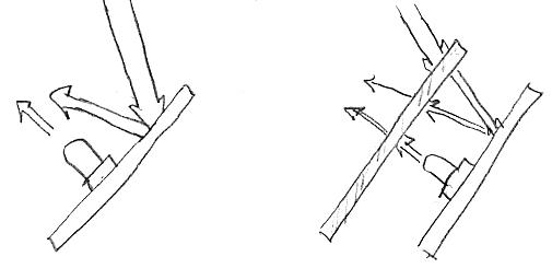
It was long ago, but I vividly remember the time I took apart an old 4-banger (+, -, *, /) calculator.  When I removed the front of the calculator, which included the red plastic LED filter (or "lens" in the parlance), the numbers on the display went from looking fine to being so washed out I could barely read them.  What was going on?  The filter obviously cut down on the wimpy LED light making its way to my eyes, and one would think the more light the better.  Legibility obviously boils down to contrast, or relative rather than absolute brightness:


Above left shows a lit LED mounted on a display substrate, without a filter.  The ambient light is much brighter, and when it reflects off of the substrate some fraction of it also makes it to your eye, washing out the LED.  On the right the filter lowers the LED brightness, but this is more than offset by the fact that the ambient light has to pass through the filter twice before reaching your eye.  If the filter is colored the same color as the LED light, then you have an optical bandpass filter which gives ambient light a triple whammy gauntlet to run.  Making the substrate flat black would also help.

So on the D-Lev I could make all the tuner LEDs the same color, say red or green or blue, and then use a same colored filter to really heighten the contrast, and I'm sorely tempted to do this.  The main reasons not to do this are:

1. A monochromatic tuner might be kind of boring looking?
2. A neutral medium smoked plastic filter could also include the LCD display behind it, thus easing manufacturing.

But perhaps the LCD shouldn't be behind a smoked filter as it is actually entirely readable in bright light (it's one of those dual mode types that works via both transmission and reflection).  And an all-one-color tuner might actually look kinda nice?  Maybe green because human eye sensitivity peaks there?  Or maybe blue or red because ambient light is less likely to have energy in those regions?  I suppose I'm leaning towards blue, mainly because of the novelty factor (we only recently got blue LEDs so there's a technical freshness to their presence).  And what about color blindness?

I've been on the fence regarding this issue (same filter for LCD & LED, or not) for a long time.

Posted: 2/2/2020 9:58:10 AM
pitts8rh

From: Minnesota USA

Joined: 11/27/2015

I did some experiments on this with the tuner back before I built my current theremin.  I have a sample book of Roscolux Cinegel color filters that I tried with various combinations of the standard color LEDs that came with the 10mm assortment that we buy for the D-Lev.  I never found any combination that was satisfactory other than to use a filter color closely matching that of the LEDs (if all are the same color) or use a neutral gray for multicolor LEDs to enhance contrast for the reason you described above.

Your explanation above is correct in showing how filtering works. For filters matching the color of the the LEDs, the percent transmission can be chosen to be low enough to just sufficiently blacken the background (benefited by 2-way light attenuation) while losing very little of what you want to see due to the one-way reduction of the in-band LED color.  Reducing the transmission % any further beyond this will then reduce contrast, which is generally not what you want. The case is almost the same with neutral gray filtering, except you don't have the benefit of the extra background darkening that you sometimes get if the extraneous things like the pcb are a different color from the filter (say a green board with red LEDs and filter).  With gray you attenuate all desired source light directly by the less-than-100% transmission percentage (or <1 transmission factor), while the background is attenuated by the transmission factor squared. As described earlier, you reach peak contrast when the transmission percentage is just low enough to blacken the background, and beyond that you lose contrast.  Either way, filtering to a point is a good thing.

I am surprised at the pieces of electronic gear with monochromatic displays that come without matching filters to enhance contrast.  Even with bright red segments some of these 7-segment displays are quite hard to read in ambient light because of either white unlit segments and/or white bezels.  I often just take things apart and apply self-stick color film.  The octave 7-segment display on my tuner has blue film overlay, and I may have applied an overlay to the tuner that I built for you (or I intended to). 

I like blue myself, but for a tuner with closely spaced LEDs or one set some distance away (separate like mine) it is not the best color due to the eye's inability to focus and resolve very well at that end of the spectrum.

I have also found that I also prefer the tuner LEDs sticking out out of the enclosure (manufacturability aside), but for the stealth look a neutral gray transparent cover and black solder mask on the pcb would pretty much hide everything while still allowing a choice of colors.

As far as the backlit LCD display goes, in normal lighting filtering doesn't accomplish much of anything except to darken it and reduce contrast.  The backlight overwhelms the reflected contribution so much that it is difficult to see any improvement, except possibly in very bright ambient conditions.  In that case the benefit of two-way attenuation of the ambient incident and reflected light might (I haven't tried this) exceed the one-way loss of the backlight, possibly resulting in a contrast improvement under those specific conditions.

I don't see any great benefit to filtering the LCD unless you like the stealth look.  And if you want the LCD to be a different color, it would be better to use a different backlight color.

Posted: 2/3/2020 3:08:48 PM
dewster

From: Northern NJ, USA

Joined: 2/17/2012

"I did some experiments on this with the tuner back before I built my current theremin.  I have a sample book of Roscolux Cinegel color filters that I tried with various combinations..."  - pitts8rh

OK, I'm seriously in awe of your scientific method!  All I've done in this regard is to just get a few samples of various gray acrylic sheet material from a "cutter" on eBay.  IIRC the Lexan Margard MR10 Solar Gray seemed like the best fit for the LCD, but perhaps not quite dark enough for the LEDs (it seems to be a 50% transmission neutral filter?).  It's probably too much of a tradeoff to do both LCD and LEDs with the same filter?  Seems that way anyway with my minimal impromptu testing.

"For filters matching the color of the the LEDs, the percent transmission can be chosen to be low enough to just sufficiently blacken the background (benefited by 2-way light attenuation) while losing very little of what you want to see due to the one-way reduction of the in-band LED color.  Reducing the transmission % any further beyond this will then reduce contrast, which is generally not what you want."

Was there a ballpark % transmission for monochromatic LEDs that seemed to work best?

"The octave 7-segment display on my tuner has blue film overlay, and I may have applied an overlay to the tuner that I built for you (or I intended to)."

Yes, I noticed the red film overlay right away when I received it, I had no idea that you applied it though - thanks!

"I like blue myself, but for a tuner with closely spaced LEDs or one set some distance away (separate like mine) it is not the best color due to the eye's inability to focus and resolve very well at that end of the spectrum."

Very good points.  Blue can be kind a fuzzy looking.  Green then?  I actually really like the white note LEDs on my tuner - we need a white filter! :-)

"I don't see any great benefit to filtering the LCD unless you like the stealth look.  And if you want the LCD to be a different color, it would be better to use a different backlight color."

Agree.  You can maybe get it with an RGB backlight, then pick the color you want after the fact.  I feel a little bad I don't have a way to control the backlight brightness - but I can't imagine ever wanting to turn it down, it's not like it's burning holes in my retina or anything.

Exposed LEDs - through holes in the panel as you do - are actually already more or less filtered with their colored milky plastic cases.  And there's a real value in being able to see the positions of the dark ones, as the overall pattern is something the eye can key off of.

I also agree on the value of different colors for the volume and note displays, particularly if viewed at a distance.

Posted: 2/3/2020 6:33:28 PM
pitts8rh

From: Minnesota USA

Joined: 11/27/2015

"Was there a ballpark % transmission for monochromatic LEDs that seemed to work best?"

The self-adhesive films that I used on our 7-segment displays just came from an art store and aren't actually gels, which are non-adhesive. They are pretty dark but have no specs.  I tracked down my gel sample book and the closest that I could find (in red for example) would suggest that less than 12% in-band transmission with a pretty sharp cutoff below 580nm is starting to be dark enough to block a green pcb, although you still might pick up glints off solder joints.  The blue that I used was closer to 8% transmission in-band.

I don't know whether green or red is better for resolving detail.  I like white as well but with the center LED in color.  As for neutral gray filtering, without the benefit of having the desired light source in a high transmittance passband, it looks like you need something in the .1% to 1% transmittance to knock the background into the black.  This would be something in the ND3 to ND2 filter range, if you have any camera filters lying about for comparison. As you would guess this has a pretty adverse impact on the LED or display brightness.

I actually do think the LCD display could stand to be dimmed a bit.  When I drag out of bed in the morning and sit down in my nice dimly-lit theremin room, I almost need sunglasses for the display.  I have a Kurzweil K2500 synth that has the same problem - all the pretty LEDs and EL displays on other equipment and this display with fluorescent backlighting is like looking at a full moon.

Posted: 2/3/2020 9:05:09 PM
dewster

From: Northern NJ, USA

Joined: 2/17/2012

"I actually do think the LCD display could stand to be dimmed a bit.  When I drag out of bed in the morning and sit down in my nice dimly-lit theremin room, I almost need sunglasses for the display."  - pitts8rh

It could certainly be arranged with another pin from the FPGA and switching transistor to do PWM, or better yet 2nd order delta-sigma or thresholded noise.  The LCD on mine is kinda dim from the droopy USB 5V powering everything, though it gets a lot brighter when I stick the USB Blaster (FPGA pumper) on it.

Posted: 2/3/2020 9:30:48 PM
dewster

From: Northern NJ, USA

Joined: 2/17/2012

The Island of Dr. Mute

I'm hopefully improving the UI preset code currently, and it's got me thinking about the mute logic. 

Right now volume mute is per preset, which is maybe a mistake?  At least I can't think of why one would want a particular voice always muted by default when switching to it?  It seems like maybe this should be a system level preset?

Anyway, there are two ways to mute:

1. rotating the mute encoder so the LCD value shows '1'
2: grounding a GPIO (general purpose in / out) pin. 

If either of these is active (i.e. calling for mute) then mute happens.

The LCD currently displays the status of the encoder mute, but not the GPIO mute. The GPIO mute might be a toggle switch which naturally displays it's state (a VOSH, or visibly obvious state holder, which I just made up!) or it could be a toggling footswitch which doesn't.  I know muting in a performance situation is super important, you want to be 100% sure at all times whether or not your instrument is muted.

So what's the logic for this?  If the GPIO mute is a VOSH, then I believe we want to always obey that if it calls for mute.  Unmuting the GPIO could either just allow the encoder mute to call the shots, or it could actually change the encoder state to unmuted.  Changing the state is interesting because then the LCD would naturally show the global muted state, not just the local encoder mute state, which would work for GPIO mutes without VOSH.

But how do we handle the situation where the VOSH GPIO isn't calling for mute but the encoder mute is?  Should we not just blindly obey the VOSH?  It could all work off of individual deltas, where we obey the mute state of a VOSH GPIO, but not the unmuted state, should the encoder then call for muting?

It probably seems like I'm making something out of nothing, but whenever there is more than one state holder, and the state can change with the preset, things can get hairy really fast.  State reduction is job #1 in this biz.

Posted: 2/4/2020 3:34:35 PM
tinkeringdude

From: Germany

Joined: 8/30/2014

It could certainly be arranged with another pin from the FPGA and switching transistor to do PWM, or better yet 2nd order delta-sigma or thresholded noise.

What is the advantage of the other two over PWM for this use case?

You must be logged in to post a reply. Please log in or register for a new account.