Let's Design and Build a (mostly) Digital Theremin!

Posted: 6/22/2020 8:08:16 PM
dewster

From: Northern NJ, USA

Joined: 2/17/2012

Tuner Doghouse

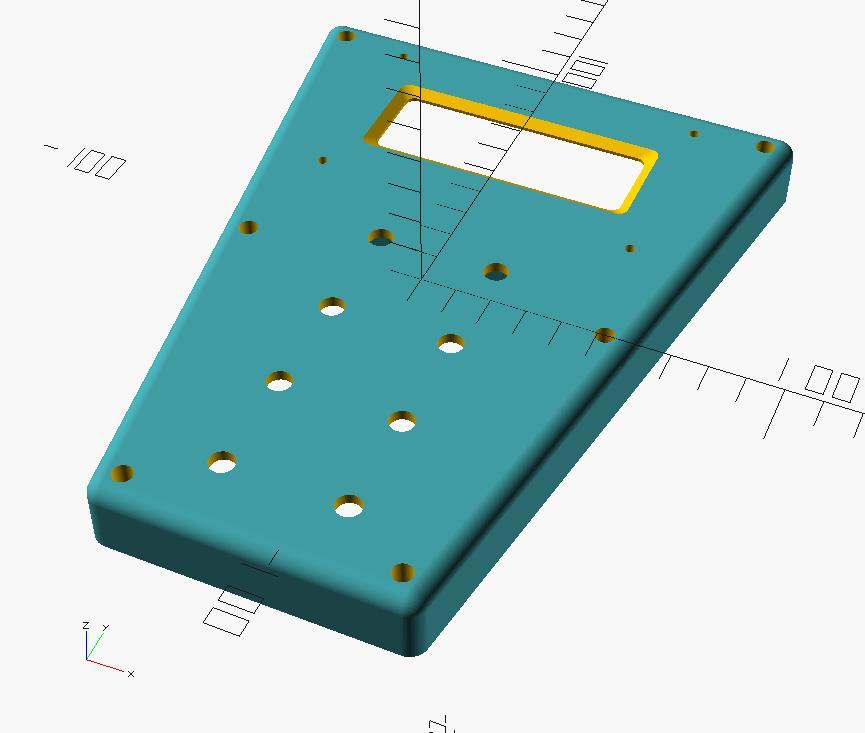
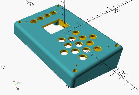
Working more on the LCD & encoders doghouse, and started in on the design of a separate angled doghouse for the LED tuner yesterday:

Face angle is currently a bit over 11 degrees, indirectly configurable by setting the front and back heights and other bulk parameters.  Mounting is via countersunk screws in the corners, the PWB mounts via thru holes in the face (figuring on stainless Allen key cap screws here which can look rather sharp, I don't trust the shallow self-tapping sort here).  Ran out of time to print a 1/2 scale today, will give that a shot tomorrow.

Posted: 6/23/2020 2:27:28 AM
dewster

From: Northern NJ, USA

Joined: 2/17/2012

Sentimental Journey

[MP3] done with my recent bass clarinet patch, only played it through 4 times or so up to now.  The opening and predominant interval is interesting because it matches my open-closed fist sensitivity setting (1/3 octave).  On top of it being a new-to-me song (hence the roughness) I haven't really played Theremin for a few weeks now (hence the extra roughness) - too busy doing the 3D printing thing (though I'm hoping some new voice will sufficiently entice Roger into updating his D-Lev SW & firmware & presets. ;-)

I've tried to dial up Sax and Oboe and a better flute, but they're all fighting me - the stars have to align or something.

Posted: 6/23/2020 4:09:28 PM
dewster

From: Northern NJ, USA

Joined: 2/17/2012

Half Scale Doghouses

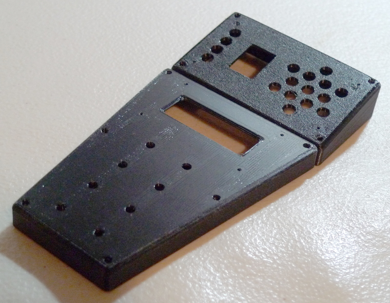
Printed up the tuner doghouse this morning at 1/2 scale.  Here it is with the LCD & encoders doghouse (which has been sanded somewhat):

I've got the black end gamma cranked way up to show detail here.  There's some spiderwebbing going on with PETG, and the first layer always has adhesion issues associated with small holes, hopefully some filler-type paint will make things better.  I wish it looked as smooth as the rendering!

Since printing the lower doghouse I've centered up the encoder holes better, and put less of an extreme horizontal angle on the LCD bezel hole (the extreme angle looks spiffy in rendering but doesn't print well).

Posted: 6/23/2020 6:45:33 PM
pitts8rh

From: Minnesota USA

Joined: 11/27/2015

"I haven't really played Theremin for a few weeks now (hence the extra roughness) - too busy doing the 3D printing thing (though I'm hoping some new voice will sufficiently entice Roger into updating his D-Lev SW & firmware & presets. ;-)" - Dew

Ha!  Sucked into the black hole of 3D printing. Same here - I was off the theremin for a couple weeks while I was in a death struggle with one of my printers, but I'm back at the theremin now.  As far as the D-Lev update goes, you should know that I just yesterday updated my Mozilla Thunderbird from v30-something to v68, and I've been clicking through the Win10 update nag screens for probably a year. I'm only, what, a year behind on the D-Lev updates?  Pffft.

Except for the boards all of the parts for the D-Lev II, which will run the latest everything, have trickled in (I just got a box of spdif decoders last week).  I'll get there on the Pro. Eventually.

"There's some spider webbing going on with PETG, and the first layer always has adhesion issues associated with small holes, hopefully some filler-type paint will make things better."

If your extrusion is being dragged away by the nozzle when your first circles print around the holes, try printing hotter.  Hair spray on the bed always helps overall adhesion, but nothing makes the first layer stay put like printing very hot and very fluid.  If you have birds in your house don't do this as the neurotoxins released by hot  PTFE will kill them, but otherwise try printing the first layer up to 250C, which I think is the generally accepted top end for Bowden systems.  With an all-metal hot end I'm printing some PETG gears at 260C with virtually no stringing, and embedded text in the gear faces is coming out sharp and clear. And the neurotoxins haven't affected me at all at all.

BTW, I had to spend some time working on gears in OpenSCAD.  I'm glad it's working for you, but omgwtf.  That is all.

Posted: 6/23/2020 7:37:49 PM
tinkeringdude

From: Germany

Joined: 8/30/2014


BTW, I had to spend some time working on gears in OpenSCAD.  I'm glad it's working for you, but omgwtf.  That is all.

First he tried the parametrics, now needs the paramedics, oh oh!

It may not be the most beautiful language ever created to do that. But the goal of assembling geometry by formulae, basically, makes a lot of sense, especially when creating things like gears and other things with obvious patterns (like the LED hole pattern in above posts), which would be fiddly and error prone to create by hand in a graphical modeler.
Which is quite evidenced by the fact that things like gears, or in architecture, stair cases, etc, are usually an existing function of the package, because no-one sane would like to do that by hand.
In OpenSCAD, you just don't wait for some company to implement what you need, you do it yourself.

And you can use e.g. git to track your changes, in a somewhat meaningful und understandable way, on the source files.

Posted: 6/23/2020 9:48:47 PM
dewster

From: Northern NJ, USA

Joined: 2/17/2012

"...try printing the first layer up to 250C, which I think is the generally accepted top end for Bowden systems.  With an all-metal hot end I'm printing some PETG gears at 260C with virtually no stringing, and embedded text in the gear faces is coming out sharp and clear."  - pitts8rh

I'm currently printing at 240/80, will try 250, thanks!

"And the neurotoxins haven't affected me at all at all."

Struggling and failing to come up with pithy quote... (I keed)

"BTW, I had to spend some time working on gears in OpenSCAD.  I'm glad it's working for you, but omgwtf.  That is all."

I totally get that.  OpenSCAD needs more fundamental 2D & 3D types, and the 3D transforms leave much to be desired.  Though, to be fair, the basics are there to roll your own personal library.  What's really missing is a way to automate/calculate complex intersections and tangents.  Edge chamfers / radii would go a long way too, though that can be a really deep subject (you often can't just willy-nilly "add" these kinds of features without geometric chaos breaking out).

The thing that bugs me the most about OpenSCAD is you can add one seemingly minor feature to your design and the rendering window suddenly slows down to (at best) a snail's-crawl.  And my designs aren't even all that complicated!

"In OpenSCAD, you just don't wait for some company to implement what you need, you do it yourself."  - tinkeringdude

Indeed, the "openness" of OpenSCAD is it's primary advantage.  And, as you point out, text source has a lot of advantages over binary blobs.

[EDIT] For me, OpenSCAD is one of those "so near, yet so far" kinds of things.  If I could clone myself, I'd give writing something similar (but better!) a shot.
Posted: 6/24/2020 3:55:07 PM
dewster

From: Northern NJ, USA

Joined: 2/17/2012

Bob Moog & Physical Design

I have a hazy recollection that I read somewhere (airtight citation!) that the Etherwave Pro physical design was done by one or more artistic types - perhaps in some sort of competition or contest? - that Bob didn't originate it, and that his cancer was perhaps too far along for him to be super involved with the Pro at that point?  (Someone please correct me if I'm way off base here.)  The pitch arm is an interesting way to space out the antennas, and making the pitch arm "active" by placing EQ coils and such inside it ("passive" would be a more accurate EE term) is a clever way to position these somewhat C sensitive components closer to the "business end" of the pitch side, though it likely highly complicates manufacture.  I've never encountered one in the wild, but I disagree entirely with the vertical control panel positioned at an extremely awkward waist height.  And we've all seen pictures of the tragic consequences of the controls being mounted only on the PWBs when the thing gets pushed over and lands on the knobs.

The Pro makes me wonder how much physical design was originated / implemented by Bob in his various designs.  I can imagine things that are pretty simple like the Melodia, or the Etherwave Standard / Plus (EWS+) were likely his.  No disrespect, but the EWS+ strikes me as overly crude, with the obvious plumbing fixtures, and the tedious cover on/off/on/off/etc. tuning procedure it induces. 

But his keyboards and such perhaps used other creative sources for their appearance?  I'm deeply interested in this subject because physical design of a manufactured product isn't at all trivial, and musical instrument ergonomics get short shrift in general.  Beyond the circuit, the SW, even the PWB, get everything there 100% right and huge pitfalls / opportunities to screw up royally await you.  You literally can't overthink it.

Posted: 6/24/2020 5:07:26 PM
dewster

From: Northern NJ, USA

Joined: 2/17/2012

Almost

I think there is something to be said for the way some wave shaping analog Theremins "almost" get a specific sound.  If it's "almost" (but not quite) a human voice, then the listener isn't anticipating a lot in the way of vowel delta / manipulation.  If it's "almost" a violin, then the lack of bow noise or string resonance isn't unexpected or remarkable.  There's a certain expressive freedom in not nailing the real source, in amorphously floating above reality.

That said, I prefer realism.  A well done Theremin & EH Talking Machine video is almost guaranteed to blow everyone away.  And whatever realism pure wave shaping provides usually breaks down when stretched over multiple octaves.

Posted: 6/27/2020 3:27:17 AM
dewster

From: Northern NJ, USA

Joined: 2/17/2012

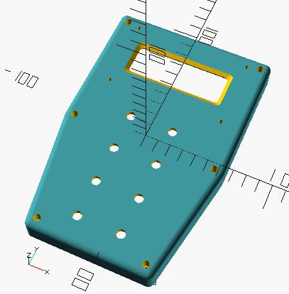
Taking the incremental skillz I picked up from doing the tuner doghouse, I re-wrote the LCD / encoder doghouse code from the ground up, and added a jaunty (?) back-to-front angle to the sides:

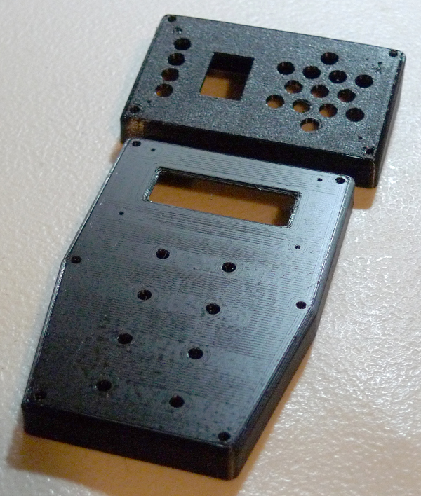
And here it is printed 1/2 scale together with the tuner doghouse:

A new TM-FLEX - Magnetic Print Surface with PEI - 235*235 from Tiny Machines arrived today (reasonable prices, super fast shipping, good packaging), so I stuck it on the Ender 3 and did this print.  Used some cheap hairspray as a mold release, parts just pop off at the end after cool-down.  No texture, but the ultra smooth surface is interesting too.  I thought the the flex plate would have PEI on both sides but the other side is just raw steel, which seems like an obvious opportunity missed.

Posted: 6/28/2020 2:08:45 AM
dewster

From: Northern NJ, USA

Joined: 2/17/2012

Canine Casa

I realized I should be considering the mounting of components other than what these doghouses are specifically housing, and so modified the LCD & encoder shell:

By extending the width of the far end linearly down it seems possible to mount the sandwich of FPGA and main board that accepts it via the LCD display holes.  These would exist in a hole cut in the top panel underneath of which the doghouse would be mounted to.  I beefed up the LCD hole mounts, as well as the main hole mounts and the stiffening ribs underneath, in order to help withstand the extra strain.

This whole 3D printing phase reminds me very much of my CNC mill programming days.  We had to make programs for everything, even one-off items customers paid for, which didn't seem all that efficient.  But you have to plan this stuff out in detail at some point during fabrication, and repeat items are that much easier once you do.

You must be logged in to post a reply. Please log in or register for a new account.