


"dewster that was very nice, a timbre to die for." - oldtemecula
Who are you, and what have you done with oldtemecula?
I've had these thoughts for some days now and am not sure how much sense it makes.
If "Cabinet" implies wood:
Electric guitar bodies these days are often made on CNC routers.
I'll concede that their cavity-to-wood ratio is probably inverse of that's needed for this project, and a bit wasteful. Or maybe it depends on the case design.
If subtractive manufacturing is used anyway.
CNC could also cut flat wood pieces precisely to save some boring manual labor, even though they then still would have to be put together.
So if that was feasible:
Are there places where, for reasonable fees, one could have one's programs run on someone elses pro grade CNC router?
As for ownership, there are also the less capable ebay china "CNC6040" (60cm x 40cm table, ~ 15..20cm height IIRC, might just be big enough) and various clones, all of different cost cutting measures, sometimes not too bad, sometimes not so good, for around 1000 bucks.
Those are quite a piece of work before one can reasonably and safely use them, though. For easy materials as medium hard woods and plastic, a lot of hobbyists seem to be happy.
That would be another place to apply the OpenSCAD skills meanwhile acquired, heh.
Although now it seems to me like you once mentioned you already had contact with these kinds of manufacturing methods, well maybe not with a lowly router and wood, more like metal mills, earlier in your work life? Or something like that...
Then you probably know these things, but I don't remember exactly.
"As for ownership, there are also the less capable ebay china "CNC6040" (60cm x 40cm table, ~ 15..20cm height IIRC, might just be big enough) and various clones, all of different cost cutting measures, sometimes not too bad, sometimes not so good, for around 1000 bucks." - tinkeringdude
Thanks! A small CNC mill does seem like a good option for minor mass production. I'll try whatever easy, cheap route I can to lower the monotony. But first, the cabinetry needs to be designed (it's all very interconnected and chicken/egg).
Hot To Go
If you find yourself engaged in Theremin design, I recommend you always have at least one fully functional unit ready to play at a moment's notice. Don't let development get in the way of doing things like practicing, trying a new song, testing out HW / SW ideas, spur-of-the-moment show-and-tell, etc. as these side activities likely contribute as much to your overall progress as do your direct efforts.
Smells Like Teen Spirit Aqua Net
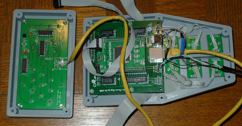
Stuck the main board sandwich and encoders in the doghouse I printed a while back, and today printed a non-angled doghouse for the tuner (using cheap hair spray as a release agent - quite fragrant!) and stuck the populated PWB in there:
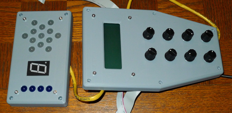
Made the tuner doghouse 20 mm deep so that it can mount flush to anything. I snipped the tuner PWB corners off so that the doghouse dimensions could be somewhat minimized.
Back to the store-bought communication knobs, the main board LCD & encoder doghouse is too thick to use the knobs I printed (will have to modify both at some point). Ribbon connectors are on order for the encoder connections to the main board, I just couldn't bring myself to use DuPonts here again. Ribbon connectors are effectively multiple DuPonts, but having a bunch of them physically ganged together seems to make everything more electrically secure?
Had the idea of printing plate / coil / AFE panels, which gives me something to do (i.e. ~procrastinate) while waiting on the connectors. For P3 I'm trying to stay as modular as possible to keep all macro ergonomic options open. A panel for each plate would form a good visual target if mounted on a larger enclosure (my current cunning plan) and would provide wide open access to the antenna & guts.
3D printing is almost like magic, and I should be utilizing it more. 2 bottom layers, 3 top layers, 2 wall layers, and 15% infill will make surprisingly rigid items (though you probably want more for structural / finished stuff). The parts Roger sent me to ogle & fondle are just incredible, dude's a master at both 3D design and printing.
Looking good, Eric! You can't beat 3D printed parts for trying out different things, especially when you can work on something else why your little robot makes them. It looks like your printer is doing a good job, judging by this and your earlier postings. It takes a while to acclimate to what a "good" 3D printed part looks like, but yours look quite clean.
I do wish that it wasn't so difficult to produce a cosmetically presentable part from an FDM type of printer, and unfortunately the SLA printers are best suited for small parts and are quite expensive to run. I keep thinking that an FDM printed part of complex shape could be nicely finished (just once) and used to make a mold for limited production of gel-coated glass-resin shells. This method is used for production of short-run RC models, so it's entirely possible to do for a theremin. It probably would not be practical if the enclosure shape was attainable by woodworking methods or machining, but for curves and interesting shapes it's a thing. I've been through this whole moldmaking process several times, and it's kind of fun in a masochistic sort of way. Making the mold is a bit of front-end work but once this is done you could probably create a set of nice shiny prefinished theremin shells in a couple hours.
I can't get over how rigid and light a thin slab of internally webbed PLA can be. If I was still flying RC I'd be all over this. PETG isn't quite as rigid, but then it won't droop in the sun either.
BTW, the new encoder boards that I have in process have dual 4x2 ribbon connectors so that I can get away from the hardwired connections to individual boards (which was a necessity for my curved "Pro" front panel). The downside is that the spacing of the knobs is no longer tweakable without making new boards. I don't know if I have those PCBs uploaded or if you have seen them but they are designed this way to allow the 16-wide (connectorized as 8x2) ribbons from the MAIN FPGA to be split in two for the connections on the single encoder board. Something to think about going forward.
I remember now when I was working at a place years ago where they always had the newest stuff in tech, and they had a huge 3D printer which was able to work with several different materials at the same time, so you could do something that had rubbery parts and rigid parts etc.
But what seemed most extending of what you could do with a 3D printer was that one of the materials it could handle was a support material that can later be easily removed, and only serves the purpose of being able to print something "in the air", well, where air will be later after removing that stuff - i.e. overhanging structures, that would otherwise just fall on the ground level.
I wonder whether by now, there are hobbyist printers that support at least two materials "at the same time", one of which could be such a support material.
I wonder whether by now, there are hobbyist printers that support at least two materials "at the same time", one of which could be such a support material. -tinkeringdude
Actually dual extrusion 3D printers are now fairly common, either to print multiple colors of standard filament, or to allow the use of a water-soluble PVA material as the second filament for support structures as you suggest.
Single material support structures are commonly used but the problem comes when you try to remove them. The top of the support structure must be printed with a fairly open grid and also needs to have a one-layer-height space above it before the overhang of the part begins printing. This provides a minimum amount of bonding and contact area so that the support can be broken away, but as you might guess it leaves the bottom of the overhang quite rough.
With the soluble material the support can be printed with a 100% fill smooth top, and the next layer of regular material (PLA or PETG, etc) can print right on it. The support is later washed away, leaving a smooth-bottom overhang.
Many printers can be retrofitted with dual extruders, but the greater moving mass generally slows the printing process a bit.
Little Boxes Made Of Ticky-Tacky PLA
Printed out some test patterns today (using 1/10 of a reel of PLA per very experimental D-Lev part was freaking me out a little):
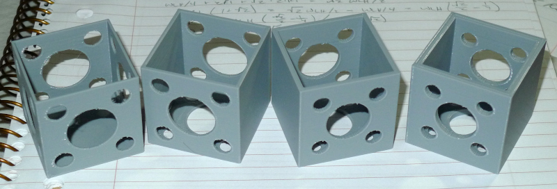
A 40mm cube with weight / material reducing holes, with various wall thicknesses: 1, 1.5, 2, 3mm. All except the 3mm have solid walls, the 3mm employs cubic 20% fill. The 3mm actually uses roughly the same material as the 2mm but is significantly more rigid. Turning on / off the holes for adjacent sides lets you subjectively test the rigidity for both (holed and non-holed) via squeezing. I'll probably go with 2.5mm for my plate side supports.
The holes are spaced one radius away from the walls and each other, which I read was the structural thing to do on some random motorcycle website (seems reasonable, who knows?).
SCAD file: [LINK]
Tinfoil Hat Brigade
It's been a challenge to keep my brain open to new possibilities and out of old ruts. I mean, why use anything structural when you don't have to? Like if the plates are going to be enclosed, use aluminum foil instead of flashing, and make the foil support super flimsy. Here's my latest plate concept printed 50% size:
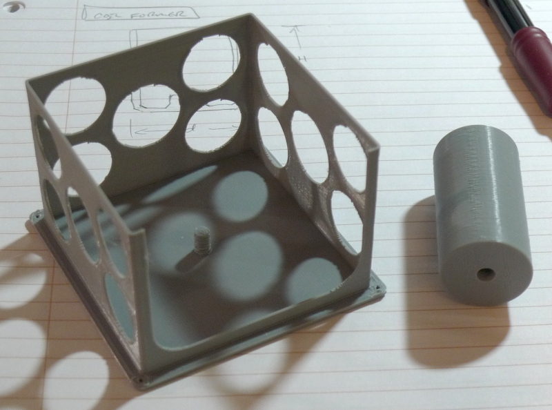
Above: The 155mm x 155mm front plate (facing down here) has a lightweight 3 wall structure on the back to support the sides of the plate, and a threaded stud to accept the coil former on the right. Leaving one side open helps access during construction, and having 3 contiguous sides of support means one can cover two of them as one wishes, leaving the third for AFE mounting.
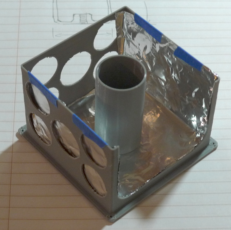
Above: one piece of foil covers the bottom and two opposing sides, with the coil form (diameter 50mm x 100mm long) screwed in place - I would use this configuration for the pitch axis (for the volume axis I would probably cover two adjacent sides). Some painter's tape holds the foil ends in place. On the full-size deal I'd like to use something between thin-assed aluminum foil and aluminum flashing just to keep it from getting inadvertent punctures and wrinkling when assembling - suggestions? I'm thinking catering supplies (and again I'm probably making things too structural for their own good).
Cura is telling me the full sized print would take 1/10 of a reel and over 10 hours - eek! I do like the idea of printing my own coil forms (I believe Roger did this first).
You must be logged in to post a reply. Please log in or register for a new account.

