Let's Design and Build a (mostly) Digital Theremin!

Posted: 10/13/2020 7:25:51 PM
dewster

From: Northern NJ, USA

Joined: 2/17/2012

Four Ears Good, Two Ears Bad

Roger raised the resonator "zing" issue and has been helping me tune the resonator internal low pass filter scaling.  Which I feel is kinda done, at least for the time being.  Here's the current solution I came up with yesterday and worked out through 20 or so test loads:

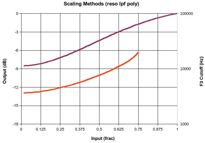
In the above graph, the purple line is that of the scaling polynomial:

  0.375 + x^2 - (0.375 * x^4)

And the red line is the resulting -3dB cutoff point (F3).  Note that the filter response is undefined above Nyquist, but it disappears before that because the attenuation is less than -3dB, but the filter continues to become more and more of a wire as the frequency input value (as produced by the polynomial) approaches 1.

This fourth order polynomial scales the inharmonic resonator "reso" raw knob value for use as the internal low pass filter corner frequency input.  We want a sinusoid type response in the log domain which starts and ends rather horizontally.  It doesn’t need much dynamic range because recirculation multiplies the attenuation, and there is a second explicit gain factor in the loop (also controlled by the "reso" knob, but exponentially).  The low end flat region reduces feedforward "zing" and the high end flat-ish region allows full feedback for bells and such.

The second order term plus offset upwardly inflects the start, and subtracting the fourth order term inflects the end back down.  Interestingly, changing the single polynomial coefficient used to both scale the fourth order term and offset the second order term alters the dynamic range while providing the same basic shape over much of it, so this could perhaps be used as an input “darkness” parameter if so desired.  The value 0.375 establishes the minimum F3 as 3.66kHz, which is somewhat higher than I was expecting to finally set it, based on my earlier observations.

I also lowered the dynamic range of the explicit "reso" gain factor from 84dB to 72dB, which helps to center things up knob-wise and makes the response more even over the full range of frequency settings of the resonator.

This has been one of the more subjective / subtle of parameter scalings, and the dudes who design reverbs for a living and do it well have my full respect.

This exercise forced me to use Libre Office Calc a bit more, and it's really not all that bad, though it feels somewhat less tightly connected to mouse actions and such.  It's so very nice that entirely viable options exist outside of Excel, and they're free!

Posted: 10/14/2020 1:25:08 AM
dewster

From: Northern NJ, USA

Joined: 2/17/2012

"I have to say again that your prints are looking very good.  The lower three look exceptional and especially so considering that they are half scale.  The internal hole strings are almost unavoidable."  - pitts8rh

Thanks!  And these are coarse Z step prints with zero cleanup.  Your prints though are works of art.

"I know you're trying to minimize time and material but you may want to just leave the ribs out and do a few millimeters of infill grid with a couple top layers.  It will make the foil easy to apply but will provide more ESD protection.  I wouldn't count on the printed plastic to provide much of a discharge barrier compared to a solid plastic, so an air gap is probably better to have."

It's probably not obvious, but that's exactly what I'm doing with the ribless one on the right, where the additional 7mm backplate added to the 5mm frontplate gives 12mm total cubic infill.  It does take a bit more material and time, but seems as good at keeping warping down as the ribs.  And it will be easier to cover with foil.

"You would probably really appreciate having a textured flex plate at some point.  It makes the first layer a little easier to lay down and it looks pretty too."

I would have bought one back when I got the flat flex plate (which has been fantastic BTW) but they were out of stock.

"And I think I mentioned it before but if you want to try a different surface appearance you can in Cura change the top/bottom line directions (under Shell) and infill line directions (under Infill) from the default 45 and 135 degrees to 0 and 90 by replacing the "[]" with [0,90]. I've started doing this for a lot of things because getting rid of the diagonal lines makes the part look a little less printed."

I was doing [0,90] but stopped when I noticed the top and bottom layers weren't tracking when they met without infill.  Cura wanted to do the final bottom layer and the first top layer in the same direction, even though they were touching each other.  I just never went back, and figure I'll have to use some kind of filler & paint anyway.

"The 912ef289.spi load is the best yet.  I'm able to have plenty of low- and mid-resonance on the strings without fighting the treble resonances.  Although they are still there they seem to be much more naturally muted, and they are easier to control with oscillator pmod and filtering or by simply compensating with playing technique.  I'm finding that when spinning through all of my various string mutations that were previously abandoned they are now usable with only a few tweaks.  I don't even know where many of these originated (violin, cello, etc) but they all sound different and most are working very well over several octaves. It's easy to come up with dozens of variations that all sound good.  These changes were worth the effort, and I hope that we can stick with this version for a while.

I'm glad it's fixing things for you!  I believe the "zing" issue is largely feedforward, so the immediate (direct + delayed once, no recirculation) peaks and dips are influenced at xmix.  Moving the reson output to post LPF causes those peaks and dips to be reduced on the high end because there is less direct constructive / destructive phase mixing going on there.  Real reverberant environments absorb the heck out of highs so our ears are expecting that too.

"I went right to your vocal sample and my immediate impression was that it was a spooky sound, and then I read your similar description.  Voices, like strings, are hard to stop playing until the butt says it's time to get up and do something else.  When I'm not spinning knobs on string presets I'm working on vocals, which are equally if not more sensitive to minor variations.  I'm finding it a little hard to get comfortable with identifying which formants contribute to certain vocal attributes.  It's easy to get into a rut by making endless variations on a given voice to change the brightness or add dynamics but they don't always make it sound like a different person. And then you have to avoid getting nasally or chipmunky over pitch changes."

I agree, vocals are a challenge.  Worse than strings, when I'm editing from an existing preset it doesn't seem like minor tweaks work beyond getting a chipmunk version of the original, so the trick is to break out of the pattern somehow, but that requires leaving a local maxima through no-man's-land via the uncanny valley.  The upper formants are largely nasal, and have an subtle yet profound influence, which I suppose makes sense from an evolutionary angle: nasal passages make up a portion of the vocal fingerprints utilized by a species understandably obsessed with identity (our large-ish brains may exist mainly to track a large number of individuals and their behaviors).

Posted: 10/14/2020 8:13:27 AM
pitts8rh

From: Minnesota USA

Joined: 11/27/2015

"It's probably not obvious, but that's exactly what I'm doing with the ribless one on the right, where the additional 7mm backplate added to the 5mm frontplate gives 12mm total cubic infill.  It does take a bit more material and time, but seems as good at keeping warping down as the ribs.  And it will be easier to cover with foil." - Dewster

It would have been obvious if I had read all of what you wrote instead of just scanning it.  Sorry about that.  I do that too often, and I should know by now that you rarely miss things.

Posted: 10/19/2020 2:28:02 AM
dewster

From: Northern NJ, USA

Joined: 2/17/2012

Stiffie Joke

You read engineering rules of thumb like "stiffness goes up with the square of the height" and it fills your head full of notions that are hard to shake.  I've been ribbing up all my PETG plates to make them flatter and less rubbery, but it seems simple cubic infill is probably superior in this regard, even though the plastic being expended for that stiffens in all dimensions, and not just the desired one, which is somewhat counter-intuitive.

Above is the back of the LED tuner plate, old at top and new at bottom (full size).  This probably isn't the best example as it doesn't present with a lot of opportunity to stick a million ribs hither and yon in there, and I didn't exactly take full advantage of said opportunities either.  But I suppose that also makes it a better candidate for cubic infill therapy, which is a dead simple option as the slicer handles it automatically.  Though, as with the plate antenna, I kept the rib around the perimeter.  There's so much to learn about physical design.

Posted: 10/24/2020 2:58:35 PM
dewster

From: Northern NJ, USA

Joined: 2/17/2012

Negative Capacitance

So I've got the NPN-based differential LC oscillator [LINK] still running on my bench and noticed something rather weird. 

1. When I bring my hand closer the antenna, the trace on the 16.6667ms delayed scope moves to the to the right.  This makes sense because the increased capacitance slows the oscillator down.

2. But when I bring my hand closer to the antenna with the pitch plate of my D-Lev P2 (which is not  powered) in the way (the plate is maybe 2' away from the differential oscillator rod antenna), the wave moves to the left and quite markedly so!  I guess the unpowered D-Lev plate is serving as the C field destination of my hand, removing C from the differential oscillator antenna rod.  The speed up effect is quite large, larger than the slow down effect of my hand alone.  It behaves almost like there's a negative hand operating on the D-Lev, but it's influencing the antenna behind it.  And when my hand gets very near the plate the wave then moves to the right!  Weird...

'

[EDIT] I put a bigger antenna on it and now it does just the opposite with the plate in between!  Weird...

Posted: 10/24/2020 3:11:59 PM
tinkeringdude

From: Germany

Joined: 8/30/2014

Dude! Negative capacitance! Can you make a Free Energy device out of that?
(or at least a flux capacitor. But you'd still need the 1.1 Jiggawatts, so free energy would sure come in handy.)

Posted: 10/24/2020 4:56:52 PM
dewster

From: Northern NJ, USA

Joined: 2/17/2012

1.21GW + DeLorean!

Posted: 10/24/2020 8:23:36 PM
Buggins

From: Porto, Portugal

Joined: 3/16/2017

Very strange effect. Who can explain it?

Posted: 10/25/2020 10:48:53 AM
pitts8rh

From: Minnesota USA

Joined: 11/27/2015

I suppose this could (given the right geometries and test conditions) be caused by a shielding or distortion effect of having the conductor in the "antenna's" E-field.

Looking at a time snapshot of the antenna here (to consider the electric field to be momentarily static) it is just a rod-shaped capacitive element surrounded by equipotential electric-field surface contours that vary in shape with distance.  Near the rod the equipotential contour is nearly a cylinder with hemispherical ends, like an elongated capsule.  At mid-range the equipotential field contours are somewhat football-shaped, or more accurately described as prolate-spheroid shaped. And of course at long range the equipotential contours approach spheres, because at long distances the shape or aspect of the element becomes less relevent.

These equipotential voltage contours are also somewhat recognizable as constant capacitance contours, and in the case of a theremin they represent contours of constant pitch. If you try moving a conductive sphere (or your hand) around a rod antenna while maintaining a constant pitch you will find that these are the shapes that you will map out at the various distances.

Now when you introduce a conductive plate into this relatively uniform field pattern it distorts it by forcing the boundary condition of constant voltage over the shape of the plate (because it's a conductor!).  The field lines will crowd in some areas and be spread in others by forcing this boundary.

Next consider the effect on a theremin, or just the oscillator in this case.  Most players will have noticed that by placing a conductor or dielectric insulator near the theremin it will generally raise the pitch (because it's lowering the oscillator frequency) due to the either the body capacitance of the conductor or the increased C due to the increased relative dielectric constant of an insulator compared to that of air. 

So assuming that a metal plate placed within the field of the oscillator's rod element will by itself lower the oscillator frequency somewhat (let's call this reference frequency f), it could be reasoned that a hand approaching behind the plate (but still at a distance so as to be in the unperturbed E-field)  will first lower the oscillator frequency below f as expected, but then as the hand becomes "hidden" by the plate (by moving into a region of less-crowded E-field lines) the frequency will try to rise toward f, although it would never quite reach it because your arm would still be in the unperturbed outer field region.  When the hand continues to move past the plate, closer to the rod and again back into the unperturbed field contours, the frequency will again continue to drop as expected.  This may be what causes the "hump" in Dewster's first observation, but you would understandably need a very specific set of conditions to exhibit the reversal effect.  Maybe that's why changing the rod antenna size made the effect disappear.

Or not... I'm sort of speculating, but this does feel familiar even if I haven't thought it through correctly.  It's something like 4:30AM here and sometimes I'm afraid posting right after I get up in the morning is like drunk-texting.  At least I can edit when I wake up.  That said, I think I have run into this kind of behavior before but at higher frequencies where "antennas" are actually antennas, so it may be due to different factors.

Posted: 10/25/2020 1:25:01 PM
dewster

From: Northern NJ, USA

Joined: 2/17/2012

"So assuming that a metal plate placed within the field of the oscillator's rod element will by itself lower the oscillator frequency somewhat (let's call this reference frequency f), it could be reasoned that a hand approaching behind the plate (but still at a distance so as to be in the unperturbed E-field)  will first lower the oscillator frequency below f as expected, but then as the hand becomes "hidden" by the plate (by moving into a region of less-crowded E-field lines) the frequency will try to rise toward f, although it would never quite reach it because your arm would still be in the unperturbed outer field region.  When the hand continues to move past the plate, closer to the rod and again back into the unperturbed field contours, the frequency will again continue to drop as expected.  This may be what causes the "hump" in Dewster's first observation, but you would understandably need a very specific set of conditions to exhibit the reversal effect."  - pitts8rh

That's what I think too.  The hand is hidden by the plate when very close, removing its C from the total contribution "seen" by the rod.  The C field can be quite complex, thus the lack of simple closed-form equations for anything outside of toy problems like concentric spheres and such, and the necessary reliance on FEA to accurately quantify C in real-world scenarios.

"Maybe that's why changing the rod antenna size made the effect disappear."

The lager rod antenna makes it reverse, the lower graph flips and the hump turns into a dip.  Which I guess also makes sense, because the larger antenna can "see around" the plate better?

What most surprised me was the strength of the effect, but maybe that's not so surprising after all, because of course hand nearness to the plate should be a big factor.

Along these lines: it's been a while since I pondered Theremin active electrostatic shielding, but there are many benefits to it.  It can shape the field to somewhat exclude both general and gestural interference, making it easier to play around others (fellow musicians on stage, nearby audience, etc.).  And it can raise the theoretical maximum LC frequency deviation (i.e. absolute sensitivity) by reducing the intrinsic C of the antenna (a big area antenna can "look" like a smaller area antenna intrinsically, but still interact mutually with the hand like a big area antenna).  AFAICT it requires HV low Z active drive, and can't be accomplished (when applied at or very near the antenna anyway) via passive means.  Good active shielding could reduce the need for HV swing in order to overcome RF interference and the like, which could lower the necessary HV supply.  A plate antenna is probably the easiest geometry to shield (a double plate - like a capacitor - is nicely symmetric)?

You must be logged in to post a reply. Please log in or register for a new account.